
Page 123 - Handbook of Civil Engineering Calculations, Second Edition
P. 123
1.106 STRUCTURAL STEEL ENGINEERING AND DESIGN
2. Compute the value of K x L
associated with a uniform-
strength column, and compare
this with the actual value
Thus, K x L 1.73(15.3) 26.5 ft (8.1
m) < 30 ft (9.2 m). The section is there-
fore inadequate.
3. Try a specific column section
of larger size
FIGURE 13 Trying W8 48, the capacity 200 kips
(889.6 kN) when K y L 17.7 ft (5.39 m). For
uniform strength, K x L 1.74(17.7)
30.8 > 30 ft (9.39 m > 9.2 m). The W8
48 therefore appears to be satisfactory.
4. Verify the design
To verify the design, record the properties of this section and compute the slenderness ra-
tios. For this grade of steel and thickness of member, the yield-point stress is 50 kips/sq.in.
2
(344.8 MPa), as given in the Manual. Thus, A 14.11 sq.in. (91038 cm ); r x 3.61 in.
(91.694 mm); r y 2.08 in. (52.832 mm). Then K x L/r x 30(12)/3.61 100; K y L/r y
15(12)/2.08 87.
5. Determine the allowable stress and member capacity
From the Manual, f 14.71 kips/sq.in. (101.425 MPa) with a slenderness ratio of 100.
Then P 14.11(14.71) 208 kips (925.2 kN). Therefore, use W8 48 because the ca-
pacity of the column exceeds the intended load.
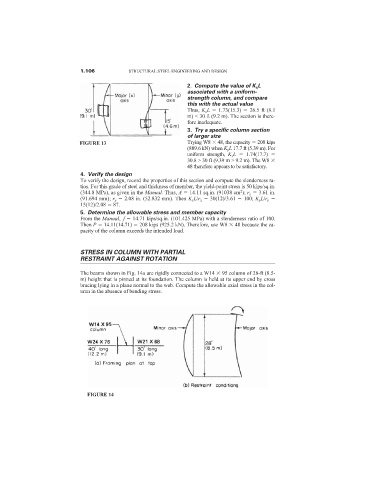
STRESS IN COLUMN WITH PARTIAL
RESTRAINT AGAINST ROTATION
The beams shown in Fig. 14a are rigidly connected to a W14 95 column of 28-ft (8.5-
m) height that is pinned at its foundation. The column is held at its upper end by cross
bracing lying in a plane normal to the web. Compute the allowable axial stress in the col-
umn in the absence of bending stress.
FIGURE 14