
Page 119 - Handbook of Civil Engineering Calculations, Second Edition
P. 119
1.102 STRUCTURAL STEEL ENGINEERING AND DESIGN
4
3
4
4
4
I (1/12)(0.25)(8.44) 12.52 in (521.121 cm ) > 3.42 in (142.351 cm ). This is
acceptable.
The stiffeners must be in intimate contact with the compression flange, but they may
terminate 1 /4 in. (44.45 mm) from the tension flange. The connection of the stiffeners to
3
the web must transmit the vertical shear specified in the Specification.
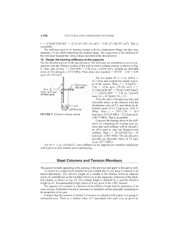
13. Design the bearing stiffeners at the supports
Use the directions given in the Specification. The stiffeners are considered to act in con-
junction with the tributary portion of the web to form a column section, as shown in Fig.
2
9. Thus, area of web 5.25(0.438) 2.30 sq.in. (14.839 cm ). Assume an allowable
stress of 20 kips/sq.in. (137.9 MPa). Then, plate area required 207/20 – 2.30 8.05
2
sq.in. (51.938 cm ).
Try two plates 10 /2 in. (254.0
1
12.7 mm), and compute the column capaci-
ty of the section. Thus, A 2(10)(0.5) +
2
2.30 12.30 sq.in. (79.359 cm ); I
3
4
4
(1/12)(0.5)(20.44) 356 in (1.4818 dm );
r (356/12.30) 0.5 5.38 in. (136.652
mm); L/r 0.75(68)/5.38 9.5.
Enter the table of slenderness ratio and
allowable stress in the Manual with the
slenderness ratio of 9.5, and obtain an al-
lowable stress of 21.2 kips/sq.in. (146.17
MPa). Then f 207/12.30 16.8
FIGURE 9. Effective column section. kips/sq.in. (115.84 MPa) < 21.2 kips/sq.in.
(146.17 MPa). This is acceptable.
Compute the bearing stress in the stiff-
eners. In computing the bearing area, as-
sume that each stiffener will be clipped 1
in. (25.4 mm) to clear the flange-to-web
welding. Then f 207/[2(9)(0.5)] 23
kips/sq.in. (158.6 MPa). The Specification
provides an allowable stress of 33 kips/
sq.in. (227.5 MPa).
The 10 /2 in. (254.0)(12.7 mm) stiffeners at the supports are therefore satisfactory
1
with respect to both column action and bearing.
Steel Columns and Tension Members
The general remarks appearing at the opening of the previous part apply to this part as well.
A column is a compression member having a length that is very large in relation to its
lateral dimensions. The effective length of a column is the distance between adjacent
points of contraflexure in the buckled column or in the imaginary extension of the buck-
led column, as shown in Fig. 10. The column length is denoted by L, and the effective
length by KL. Recommended design values of K are given in the AISC Manual.
The capacity of a column is a function of its effective length and the properties of its
cross section. It therefore becomes necessary to formulate certain principles pertaining to
the properties of an area.
Consider that the moment of inertia I of an area is evaluated with respect to a group of
concurrent axes. There is a distinct value of I associated with each axis, as given by