
Page 115 - Handbook of Civil Engineering Calculations, Second Edition
P. 115
1.98 STRUCTURAL STEEL ENGINEERING AND DESIGN
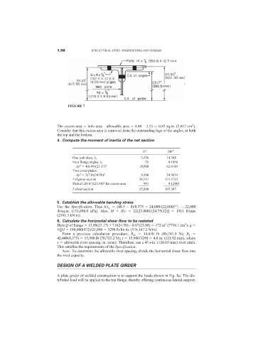
FIGURE 7
2
The excess area hole area – allowable area 4.00 – 3.13 0.87 sq.in. (5.613 cm ).
Consider that this excess area is removed from the outstanding legs of the angles, at both
the top and the bottom.
4. Compute the moment of inertia of the net section
in 4 dm 4
3,456 14.384
One web plate, I 0
35 0.1456
Four flange angles, I 0
2
Ay 4(6.94)(23.17) 2 14,900 62.0184
Two cover plates:
Ay 2(7.0)(24.50) 2 8,400 34.9634
2
I of gross section 26,791 111.5123
4.12485
2
991
Deduct 2(0.87)(23.88) for excess area ______ _________
I of net section 25,800 107.387
5. Establish the allowable bending stress
0.5
Use the Specification. Thus h/t w (48.5 – 8)/0.375 < 24,000/(22,000) ; 22,000
lb/sq.in. (151,690.0 kPa). Also, M fI/c 22(25,800)/[24.75(12)] 1911 ft·kips
(2591.3 kN·m).
6. Calculate the horizontal shear flow to be resisted
3
3
Here Q of flange 13.88(23.17) + 7.0(24.50) – 0.87(23.88) 472 in (7736.1 cm ); q
VQ/I 180,000(472)/25,800 3290 lb/lin in. (576,167.2 N/m).
From a previous calculation procedure, R ds 18,040 lb (80,241.9 N); R b
42,440(0.375) 15,900 lb (70,723.2 N); s 15,900/3290 4.8 in. (121.92 mm), where
3
s allowable rivet spacing, in. (mm). Therefore, use a 4 /4-in. (120.65-mm) rivet pitch.
This satisfies the requirements of the Specification.
Note: To determine the allowable rivet spacing, divide the horizontal shear flow into
the rivet capacity.
DESIGN OF A WELDED PLATE GIRDER
A plate girder of welded construction is to support the loads shown in Fig. 8a. The dis-
tributed load will be applied to the top flange, thereby offering continuous lateral support.