Page 113 - Handbook of Civil Engineering Calculations, Second Edition
P. 113

1.96            STRUCTURAL STEEL ENGINEERING AND DESIGN


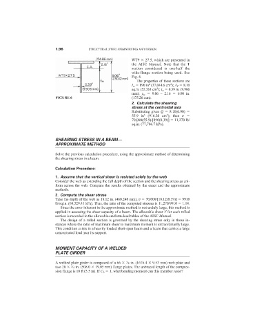
                                                                WT9   27.5, which are presented in
                                                                the AISC  Manual. Note that the T
                                                                section considered is one-half the
                                                                wide-flange section being used. See
                                                                Fig. 6.
                                                                   The properties of these sections are
                                                                                   4
                                                                        4
                                                                I w   890 in (37,044.6 cm ); A T   8.10
                                                                            2
                                                                sq.in. (52.261 cm ); t w   0.39 in. (9.906
                                                                mm);  y m   9.06 – 2.16    6.90 in.
                            FIGURE 6                            (175.26 mm).
                                                                2. Calculate the shearing
                                                                stress at the centroidal axis
                                                                Substituting gives Q   8.10(6.90)
                                                                                 3
                                                                55.9 in 3  (916.20 cm ); then  v
                                                                70,000(55.9)/[890(0.39)]   11,270 lb/
                                                                sq.in. (77,706.7 kPa).

                            SHEARING STRESS IN A BEAM—
                            APPROXIMATE METHOD


                            Solve the previous calculation procedure, using the approximate method of determining
                            the shearing stress in a beam.

                            Calculation Procedure:
                            1. Assume that the vertical shear is resisted solely by the web
                            Consider the web as extending the full depth of the section and the shearing stress as uni-
                            form across the web. Compare the results obtained by the exact and the approximate
                            methods.
                            2. Compute the shear stress
                            Take the depth of the web as 18.12 in. (460.248 mm), v   70,000/[18.12(0.39)]   9910
                            lb/sq.in. (68,329.45 kPa). Thus, the ratio of the computed stresses is 11,270/9910   1.14.
                              Since the error inherent in the approximate method is not unduly large, this method is
                            applied in assessing the shear capacity of a beam. The allowable shear V for each rolled
                            section is recorded in the allowable-uniform-load tables of the AISC Manual.
                              The design of a rolled section is governed by the shearing stress only in those in-
                            stances where the ratio of maximum shear to maximum moment is extraordinarily large.
                            This condition exists in a heavily loaded short-span beam and a beam that carries a large
                            concentrated load near its support.


                            MOMENT CAPACITY OF A WELDED
                            PLATE GIRDER

                                                             3
                            A welded plate girder is composed of a 66   /8 in. (1676.4   9.53 mm) web plate and
                                   3
                            two 20   /4 in. (508.0   19.05 mm) flange plates. The unbraced length of the compres-
                            sion flange is 18 ft (5.5 m). If C b   1, what bending moment can this member resist?
   108   109   110   111   112   113   114   115   116   117   118