
Page 110 - Handbook of Civil Engineering Calculations, Second Edition
P. 110
STRUCTURAL STEEL DESIGN 1.93
5. Ascertain whether the assumed size of the cover plates
satisfies the AISC Specification
Using the appropriate AISC Manual section, we find 7.56/0.375 20.2 < 32, which is
1
acceptable; /2(10 – 7.56)/0.375 3.25 < 16, which is acceptable.
6. Test the adequacy of the trial section
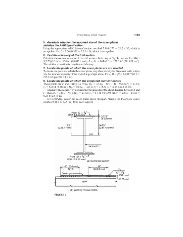
Calculate the section modulus of the trial section. Referring to Fig. 4a, we see I 984 +
3
4
3
2
4
2(3.75)(9.31) – 1634 in (68,012.1 cm ); S I/c 1634/9.5 172.0 in (2819.08 cm ).
The reinforced section is therefore satisfactory.
7. Locate the points at which the cover plates are not needed
To locate the points at which the cover plates may theoretically be dispensed with, calcu-
late the moment capacity of the wide-flange shape alone. Thus, M fS 24(107.8)/12
215.6 ft·kips (292.3 kN·m).
8. Locate the points at which the computed moment occurs
2
These points are F and G (Fig. 3). Thus, M F 35.2y 2 – 8(y 1 – 4) – /2(l.2y 2 ) 215.6;
1
2
1
y 2 8.25 ft (2.515 m); M G 30.8y 2 – /2(1.2y 2 ) 215.6; y 2 8.36 ft (2.548 m).
Alternatively, locate F by considering the area under the shear diagram between E and
2
F. Thus M F 340.3 – /2(1.2y 3 ) 215.6; y 3 14.42 ft (4.395 m); y 1 22.67 – 14.42
1
8.25 ft (2.515 m).
For symmetry, center the cover plates about midspan, placing the theoretical cutoff
points at 8 ft 3 in. (2.51 m) from each support.
FIGURE 4