
Page 108 - Handbook of Civil Engineering Calculations, Second Edition
P. 108
STRUCTURAL STEEL DESIGN 1.91
4. Calculate the allowable stress in
each interval between lateral
supports
By applying the provisions of the Manual,
calculate the allowable stress in each interval
between lateral supports, and compare this
with the actual stress. For A36 steel, the Man-
ual formula (4) reduces to f 1 22,000 –
2
0.679(L
/r) /C b lb/sq.in. (kPa). By Manual
formula (5), f 2 12,000,000/(L
d/A f ) lb/sq.in.
(kPa). Set the allowable stress equal to the
greater of these values.
For interval AB: L
8 ft (2.4 m) < L c ;
f allow 24,000 lb/sq.in. (165,480.0 kPa); f max
148,000(12)/109.7 16,200 lb/sq.in.
(111,699.0 kPa)—this is acceptable.
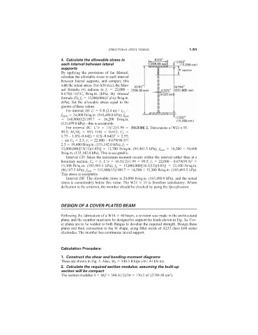
For interval BC: L
/r 15(12)/1.99 FIGURE 2. Dimensions of W21 × 55.
90.5; M 1 /M 2 95/(–148) –0.642; C b
2
1.75 – 1.05(–0.642) + 0.3(–0.642) 2.55;
2
set C b 2.3; f 1 22,000 – 0.679(90.5) /
2.3 19,600 lb/sq.in. (135,142.0 kPa); f 2
12,000,000/[15(12)(4.85)] 13,700 lb/sq.in. (94,461.5 kPa); f max 16,200 < 19,600
lb/sq.in. (135,142.0 kPa). This is acceptable.
Interval CD: Since the maximum moment occurs within the interval rather than at a
boundary section, C b 1; L
/r 16.5(12)/1.99 99.5; f 1 22,000 – 0.679(99.5)
2
15,300 lb/sq.in. (105,493.5 kPa); f 2 12,000,000/[16.5(12)(4.85)] 12,500 lb/sq.in.
(86,187.5 kPa); f max 132,800(12)/109.7 14,500 < 15,300 lb/sq.in. (105,493.5 kPa).
This stress is acceptable.
Interval DE: The allowable stress is 24,000 lb/sq.in. (165,480.0 kPa), and the actual
stress is considerably below this value. The W21 55 is therefore satisfactory. Where
deflection is the criterion, the member should be checked by using the Specification.
DESIGN OF A COVER-PLATED BEAM
Following the fabrication of a W18 60 beam, a revision was made in the architectural
plans, and the member must now be designed to support the loads shown in Fig. 3a. Cov-
er plates are to be welded to both flanges to develop the required strength. Design these
plates and their connection to the W shape, using fillet welds of A233 class E60 series
electrodes. The member has continuous lateral support.
Calculation Procedure:
1. Construct the shear and bending-moment diagrams
These are shown in Fig. 3. Also, M E 340.3 ft·kips (461.44 kN·m).
2. Calculate the required section modulus, assuming the built-up
section will be compact
3
3
The section modulus S M/f 340.3(12)/24 170.2 in (2789.58 cm ).