
Page 120 - Handbook of Civil Engineering Calculations, Second Edition
P. 120
STRUCTURAL STEEL DESIGN 1.103
earlier equations in this section. The
major axis is the one for which I is
maximum; the minor axis is the one
for which I is minimum. The major
and minor axes are referred to collec-
tively as the principal axes.
With reference to the equation
2
given earlier, namely, I x I x
cos
2
+ I y
sin – P x y sin 2 , the orienta-
tion of the principal axes relative to
the given x
and y
axes is found by
differentiating I x with respect to ,
equating this derivative to zero, and
solving for to obtain tan 2
2P x y /(I y
– I x
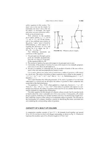
), Fig. 15. FIGURE 10. Effective column lengths.
The following statements are
corollaries of this equation:
1. The principal axes through a given
point are mutually perpendicular,
since the two values of that satis-
fy this equation differ by 90°.
2. The product of inertia of an area with respect to its principal axes is zero.
3. Conversely, if the product of inertia of an area with respect to two mutually perpendi-
cular axes is zero, these are principal axes.
4. An axis of symmetry is a principal axis, for the product of inertia of the area with re-
spect to this axis and one perpendicular thereto is zero.
Let A 1 and A 2 denote two areas, both of which have a radius of gyration r with respect
to a given axis. The radius of gyration of their composite area is found in this manner: I c
2
2
2
2
I 1 + I 2 A 1 r + A 2 r (A 1 + A 2 )r . But A 1 + A 2 A c . Substituting gives I c A w r ;
therefore, r c r.
This result illustrates the following principle: If the radii of gyration of several areas
with respect to a given axis are all equal, the radius of gyration of their composite area
equals that of the individual areas.
2
2
The equation I x I 0 + Ak , when applied to a single area, becomes I x I 0 + Ak .
2
2
2
2 0.5
2
Then Ar x Ar 0 + Ak , or r x (r 0 + k ) . If the radius of gyration with respect to a cen-
troidal axis is known, the radius of gyration with respect to an axis parallel thereto may be
readily evaluated by applying this relationship.
The Euler equation for the strength of a slender column reveals that the member tends
to buckle about the minor centroidal axis of its cross section. Consequently, all column
design equations, both those for slender members and those for intermediate-length mem-
bers, relate the capacity of the column to its minimum radius of gyration. The first step in
the investigation of a column, therefore, consists in identifying the minor centroidal axis
and evaluating the corresponding radius of gyration.
CAPACITY OF A BUILT-UP COLUMN
A compression member consists of two C15 40 channels laced together and spaced
10 in. (254.0 mm) back to back with flanges outstanding, as shown in Fig. 11. What axial
load may this member carry if its effective length is 22 ft (6.7 m)?