
Page 122 - Handbook of Civil Engineering Calculations, Second Edition
P. 122
1.105 STRUCTURAL STEEL DESIGN 1.105
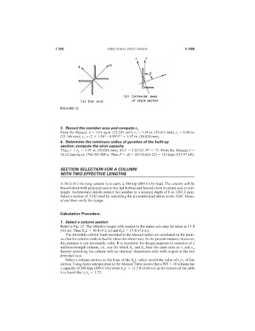
FIGURE 12
3. Record the member area and compute r v
2
From the Manual, A 3.61 sq.in. (23.291 cm ); r y 1.56 in. (39.624 mm); r z 0.99 in.
2
2 0.5
(25.146 mm); r v (2 1.56 – 0.99 ) 1.97 in. (50.038 mm).
4. Determine the minimum radius of gyration of the built-up
section; compute the strut capacity
Thus, r r p 1.97 in. (50.038 mm); KL/r 12(12)/1.97 73. From the Manual, f
16.12 kips/sq.in. (766.361 MPa). Then P Af 2(3.61)(16.12) 116 kips (515.97 kN).
SECTION SELECTION FOR A COLUMN
WITH TWO EFFECTIVE LENGTHS
A 30-ft (9.2-m) long column is to carry a 200-kip (889.6-kN) load. The column will be
braced about both principal axes at top and bottom and braced about its minor axis at mid-
height. Architectural details restrict the member to a nominal depth of 8 in. (203.2 mm).
Select a section of A242 steel by consulting the allowable-load tables in the AISC Manu-
al and then verify the design.
Calculation Procedure:
1. Select a column section
Refer to Fig. 13. The effective length with respect to the minor axis may be taken as 15 ft
(4.6 m). Then K x L 30 ft (9.2 m) and K y L 15 ft (4.6 m).
The allowable column loads recorded in the Manual tables are calculated on the prem-
ise that the column tends to buckle about the minor axis. In the present instance, however,
this premise is not necessarily valid. It is expedient for design purposes to conceive of a
uniform-strength column, i.e., one for which K x and K y bear the same ratio as r x and r y ,
thereby endowing the column with an identical slenderness ratio with respect to the two
principal axes.
Select a column section on the basis of the K y L value; record the value of r x /r y of this
section. Using linear interpolation in the Manual Table shows that a W8 40 column has
a capacity of 200 kips (889.6 kN) when K y L 15.3 ft (4.66 m); at the bottom of the table
it is found that r x /r y 1.73.