Page 125 - Handbook of Civil Engineering Calculations, Second Edition
P. 125

1.108           STRUCTURAL STEEL ENGINEERING AND DESIGN

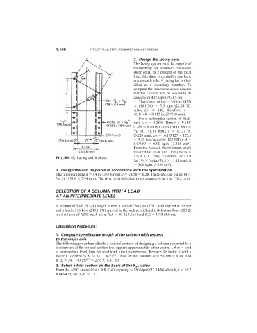
                                                                 2. Design the lacing bars
                                                                 The lacing system must be capable of
                                                                 transmitting an assumed transverse
                                                                 shear equal to 2 percent of the axial
                                                                 load; this shear is carried by two bars,
                                                                 one on each side. A lacing bar is clas-
                                                                 sified as a secondary member. To
                                                                 compute the transverse shear, assume
                                                                 that the column will be loaded to its
                                                                 capacity of 432 kips (1921.5 N).
                                                                   Then force per bar   /2(0.02)(432)
                                                                                  1
                                                                   (16.1/14)    5.0 kips (22.24 N).
                                                                 Also,  L/r   140; therefore,  r
                                                                 16.1/140   0.115 in. (2.9210 mm).
                                                                   For a rectangular section of thick-
                                                                 ness  t,  r   0.289t. Then  t   0.115/
                                                                 0.289   0.40 in. (10.160 mm). Set t
                                                                 7 /16 in. (11.11 mm);  r   0.127 in.
                                                                 (3.226 mm); L/r   16.1/0.127   127; f
                                                                   9.59 kips/sq.in.(66. 123 MPa); A
                                                                                          2
                                                                 5.0/9.59    0.52 sq.in. (3.355 cm ).
                                                                 From the Manual, the minimum width
                                                                 required for  /2-in. (12.7 mm) rivets
                                                                          1
                                                                 1
                                                                 1 /2 in. (38.1 mm). Therefore, use a flat
                            FIGURE 15. Lacing and tie plates.
                                                                    1
                                                                 bar 1 /2   /16 in. (38.1   11.11 mm); A
                                                                        7
                                                                                 2
                                                                   0.66 sq.in. (4.258 cm ).
                            3. Design the end tie plates in accordance with the Specification
                            The minimum length   14 in. (355.6 mm); t   14/50   0.28. Therefore, use plates 14
                            5 /16 in. (355.6   7.94 mm). The rivet pitch is limited to six diameters, or 3 in. (76.2 mm).
                            SELECTION OF A COLUMN WITH A LOAD
                            AT AN INTERMEDIATE LEVEL
                            A column of 30-ft (9.2-m) length carries a load of 130 kips (578.2 kN) applied at the top
                            and a load of 56 kips (249.1 kN) applied to the web at midheight. Select an 8-in. (203.2-
                            mm) column of A242 steel, using K x L   30 ft (9.2 m) and K y L   15 ft (4.6 m).


                            Calculation Procedure:
                            1. Compute the effective length of the column with respect
                            to the major axis
                            The following procedure affords a rational method of designing a column subjected to a
                            load applied at the top and another load applied approximately at the center. Let m   load
                            at intermediate level, kips per total load, kips (kilonewtons). Replace the factor K with a
                                                       0.5
                            factor K
 defined by K
  K(1 – m/2) . Thus, for this column, m   56/186   0.30. And
                            K
 x L   30(1 – 0.15) 0.5    27.6 ft (8.41 m).
                            2. Select a trial section on the basis of the K y L value
                            From the AISC Manual for a W8   40, capacity   186 kips (827.3 kN) when K y L   16.2
                            ft (4.94 m) and r x /r y   1.73.
   120   121   122   123   124   125   126   127   128   129   130