
Page 127 - Handbook of Civil Engineering Calculations, Second Edition
P. 127
1.110 STRUCTURAL STEEL ENGINEERING AND DESIGN
INVESTIGATION OF A BEAM COLUMN
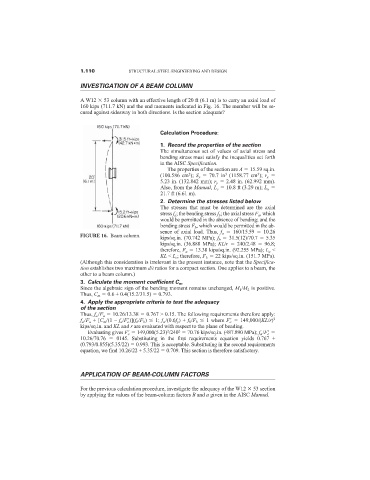
A W12 53 column with an effective length of 20 ft (6.1 m) is to carry an axial load of
160 kips (711.7 kN) and the end moments indicated in Fig. 16. The member will be se-
cured against sidesway in both directions. Is the section adequate?
Calculation Procedure:
1. Record the properties of the section
The simultaneous set of values of axial stress and
bending stress must satisfy the inequalities set forth
in the AISC Specification.
The properties of the section are A 15.59 sq.in.
(100.586 cm ); S x 70.7 in (1158.77 cm ); r x
2
3
3
5.23 in. (132.842 mm); r y 2.48 in. (62.992 mm).
Also, from the Manual, L c 10.8 ft (3.29 m); L u
21.7 ft (6.61 m).
2. Determine the stresses listed below
The stresses that must be determined are the axial
stress f a ; the bending stress f b ; the axial stress F a , which
would be permitted in the absence of bending; and the
bending stress F b , which would be permitted in the ab-
sence of axial load. Thus, f a 160/15.59 10.26
FIGURE 16. Beam column.
kips/sq.in. (70.742 MPa); f b 31.5(12)/70.7 5.35
kips/sq.in. (36.888 MPa); KL/r 240/2.48 96.8;
therefore, F a 13.38 kips/sq.in. (92.255 MPa); L u <
KL < L c ; therefore, F b 22 kips/sq.in. (151.7 MPa).
(Although this consideration is irrelevant in the present instance, note that the Specifica-
tion establishes two maximum d/t ratios for a compact section. One applies to a beam, the
other to a beam column.)
3. Calculate the moment coefficient C m
Since the algebraic sign of the bending moment remains unchanged, M 1 /M 2 is positive.
Thus, C m 0.6 + 0.4(15.2/31.5) 0.793.
4. Apply the appropriate criteria to test the adequacy
of the section
Thus, f a /F a 10.26/13.38 0.767 > 0.15. The following requirements therefore apply:
f a /F a + [C m /(1 – f a /F e
)](f b /F b ) 1; f a /(0.6f y ) + f b /F b 1 where F e
149,000/(KL/r) 2
kips/sq.in. and KL and r are evaluated with respect to the plane of bending.
2
2
Evaluating gives F e
149,000(5.23) /240 70.76 kips/sq.in. (487.890 MPa); f a /F e
10.26/70.76 0145. Substituting in the first requirements equation yields 0.767 +
(0.793/0.855)(5.35/22) 0.993. This is acceptable. Substituting in the second requirements
equation, we find 10.26/22 + 5.35/22 0.709. This section is therefore satisfactory.
APPLICATION OF BEAM-COLUMN FACTORS
For the previous calculation procedure, investigate the adequacy of the W12 53 section
by applying the values of the beam-column factors B and a given in the AISC Manual.