
Page 130 - Handbook of Civil Engineering Calculations, Second Edition
P. 130
STRUCTURAL STEEL DESIGN 1.113
Calculation Procedure:
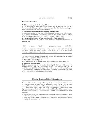
1. Show one angle in its developed form
Cut the outstanding leg, and position it to be coplanar with the other one, as in Fig. 18b.
The gross width of the angle w g is the width of the equivalent plate thus formed; it equals
the sum of the legs of the angle less the thickness.
2. Determine the gross width in terms of the thickness
Assume tentatively that 2.5 rivet holes will be deducted to arrive at the net width. Express
w g in terms of the thickness t of each angle. Then net area required 141/22 6.40
2
sq.in. (41.292 cm ); also, 2t(w g – 2.5 0.875) 6.40; w g 3.20/t + 2.19.
3. Assign trial thickness values, and determine the gross width
Construct a tabulation of the computed values. Then select the most economical size of
member. Thus
t, in. w g + t, in. Area, sq.in.
2
2
(mm) w g , in. (mm) (mm) Available size, in. (mm) (cm ) (cm )
1 /2(12.7) 8.59 (218.186) 9.09 (230.886) 6 3 1 /2 1 /2 (152.4 88.9 12.7) 4.50 (29.034)
7 /16 (11.11) 9.50 (241.300) 9.94 (252.476) 6 4 7 /16 (152.4 101.6 11.11) 4.18 (26.969)
3 /8 (9.53) 10.72 (272.228) 11.10 (281.940) None
The most economical member is the one with the least area. Therefore, use two angles
7
6 4 /16 in. (152.4 101.6 11.11 mm).
4. Record the standard gages
Refer to the Manual for the standard gages, and record the values shown in Fig. 18b.
5. Establish the rivet pitch
Find the minimum value of s to establish the rivet pitch. Thus, net width required
1 /2[6.40/(7/16)] 7.31 in. (185.674 mm); gross width 6 + 4 – 0.44 9.56 in. (242.824
2
2
mm). Then 9.56 – 3(0.875) + s /(4 2.5) + s /(4 4.31) 7.31; s 1.55 in. (39.370 mm).
For convenience, use the standard pitch of 3 in. (76.2 mm). This results in a net width
of 7.29 in. (185.166 mm); the deficiency is negligible.
Plastic Design of Steel Structures
Consider that a structure is subjected to a gradually increasing load until it collapses.
When the yield-point stress first appears, the structure is said to be in a state of initial
yielding. The load that exists when failure impends is termed the ultimate load.
In elastic design, a structure has been loaded to capacity when it attains initial yield-
ing, on the theory that plastic deformation would annul the utility of the structure. In plas-
tic design, on the other hand, it is recognized that a structure may be loaded beyond initial
yielding if:
1. The tendency of the fiber at the yield-point stress toward plastic deformation is resis-
ted by the adjacent fibers.
2. Those parts of the structure that remain in the elastic-stress range are capable of sup-
porting this incremental load.