
Page 136 - Handbook of Civil Engineering Calculations, Second Edition
P. 136
STRUCTURAL STEEL DESIGN 1.119
3, the member behaves as a mechanism (i.e., a constrained chain of pin-connected rigid
bodies, or links).
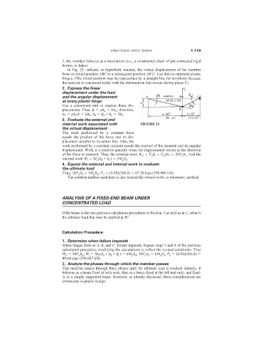
In Fig. 23, indicate, in hyperbolic manner, the virtual displacement of the member
from its initial position ABC to a subsequent position AB
C. Use dots to represent plastic
hinges. (The initial position may be represented by a straight line for simplicity because
the analysis is concerned solely with the deformation that occurs during phase 3.)
2. Express the linear
displacement under the load
and the angular displacement
at every plastic hinge
Use a convenient unit to express these dis-
placements. Thus, a A b C ; therefore,
C a A /b 2 A ; B A + C 3 A .
3. Evaluate the external and
internal work associated with FIGURE 23
the virtual displacement
The work performed by a constant force
equals the product of the force and its dis-
placement parallel to its action line. Also, the
work performed by a constant moment equals the product of the moment and its angular
displacement. Work is a positive quantity when the displacement occurs in the direction
of the force or moment. Thus, the external work W E P u P u a A 20P u A . And the
internal work W I M p ( B + C ) 5M p A .
4. Equate the external and internal work to evaluate
the ultimate load
Thus, 20P u A 5M p A ; P u (5/20)(268.8) 67.20 kips (298.906 kN).
The solution method used here is also termed the virtual-work, or kinematic, method.
ANALYSIS OF A FIXED-END BEAM UNDER
CONCENTRATED LOAD
If the beam in the two previous calculation procedures is fixed at A as well as at C, what is
the ultimate load that may be applied at B?
Calculation Procedure:
1. Determine when failure impends
When hinges form at A, B, and C, failure impends. Repeat steps 3 and 4 of the previous
calculation procedure, modifying the calculations to reflect the revised conditions. Thus
W E 20P u A ; W I M P ( a + B + C ) 6M p A ; 20P u A 6M p A ; P u (6/20)(268.8)
80.64 kips (358.687 kN).
2. Analyze the phases through which the member passes
This member passes through three phases until the ultimate load is reached. Initially, it
behaves as a beam fixed at both ends, then as a beam fixed at the left end only, and final-
ly as a simply supported beam. However, as already discussed, these considerations are
extraneous in plastic design.