
Page 169 - Handbook of Civil Engineering Calculations, Second Edition
P. 169
1.152 STRUCTURAL STEEL ENGINEERING AND DESIGN
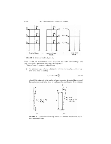
FIGURE 43. Frame models for M nt and M lt .
4
4
where K 1.0, I is the moment of inertia (in. ) (cm ) and l is the unbraced length (in.)
(cm). (Both I and l are taken in the plane of bending only.)
The coefficient C m is determined as follows.
(1) For restrained beam-columns not subjected to transverse loads between their sup-
ports in the plane of bending
M 1
C m 0.6 – 0.4 (H1-4)
M 2
(1) where M 1 /M 2 is the ratio of the smaller to larger moment at the ends of the portion of
the member unbraced in the plane of bending under consideration. If the rotations
FIGURE 44. Illustrations of secondary effects. (a) Column in braced frame; (b) Col-
umn in unbraced frame.