
Page 167 - Handbook of Civil Engineering Calculations, Second Edition
P. 167
1.150 STRUCTURAL STEEL ENGINEERING AND DESIGN
M x 200 kip-ft (271 kNm); M y 0; single-curvature bending (i.e. equal and opposite
end moments); and no transverse loads along the member. The floor-to-floor height is 15
ft (4.57 m).
Calculation Procedure:
1. Find the effective axial load for the beam-column
This procedure considers singly and doubly symmetric beam-columns: members subject-
ed combined axial compression and bending about one or both principal axes. The combi-
nation of compression with flexure may result from (either)
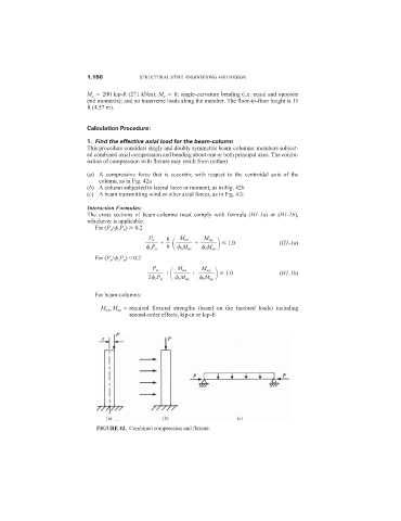
(a) A compressive force that is eccentric with respect to the centroidal axis of the
column, as in Fig. 42a
(b) A column subjected to lateral force or moment, as in Fig. 42b
(c) A beam transmitting wind or other axial forces, as in Fig. 42c
Interaction Formulas:
The cross sections of beam-columns must comply with formula (H1-1a) or (H1-1b),
whichever is applicable.
For (P u / c P n ) 0.2
P u 8 M ux M uy
+ + 1.0 (H1-1a)
c P n 9
b M nx b M ny
For (P u / c P n ) < 0.2
P u M ux M uy
+ + 1.0 (H1-1b)
2 c P n
b M nx b M ny
For beam-columns:
M ux , M uy required flexural strengths (based on the factored loads) including
second-order effects, kip-in or kip-ft
FIGURE 42. Combined compression and flexure.