Page 162 - Handbook of Civil Engineering Calculations, Second Edition
P. 162

STRUCTURAL STEEL DESIGN               1.145


                                                                       –   p
                                                 M nx   M px – (M px – M rx )
                                                                   
   r –   p
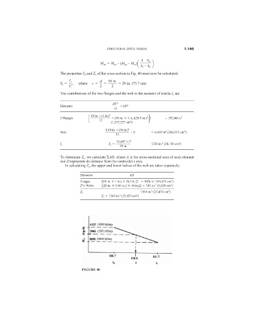
                              The properties S x and Z x of the cross section in Fig. 40 must now be calculated.
                                  I x            d   58 in.
                              S x     ,     where     c             29 in. (73.7 cm)
                                  C              2     2
                              The contributions of the two flanges and the web to the moment of inertia I x are

                                                       BT  3
                              Elements                     + AD 2
                                                        12
                                               18 in. × (1 in.) 3       2 
             4
                              2 Flanges                + (18 in.   1 in.)(28.5 in.) 2    29,244 in
                                                 12
                                                                4
                                                      (1,217,227 cm )
                                                    0.44 in. × (56 in.) 3
                              Web                               + 0         6,403 in (266,513 cm )
                                                                                          4
                                                                                 4
                                                         12
                                                         35,647 in. 4
                                                     S x                  1230 in. (20,156 cm )
                                                                                       3
                                                                               3
                              I x
                                                           29 in.
                              To determine Z x , we calculate  AD, where A is the cross-sectional area of each element
                              and D represents its distance from the centroidal x axis.
                                In calculating Z x , the upper and lower halves of the web are taken separately.
                                        Elements               AD
                                        Flanges   [(18 in.   1 in.)   28.5 in.]2     1026 in. (16,813 cm )
                                                                           3
                                                                                   3
                                        1
                                                                                   3
                                        2 /2 Webs  [(28 in.   0.44 in.)   14 in.]2   343 in. (5,620 cm )
                                                                            3
                                                                                  3
                                                                     1369 in. (22,433 cm )
                                                                          3
                                        Z x
                                                  Z x   1369 in. (22,433 cm )
                                                           3
                                                                   3


                                        FIGURE 40
   157   158   159   160   161   162   163   164   165   166   167