
Page 210 - Handbook of Civil Engineering Calculations, Second Edition
P. 210
HANGERS, CONNECTORS, AND WIND-STRESS ANALYSIS 1.193
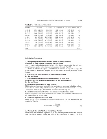
TABLE 1. Calculation of Wind Drift
4
4
Member I, in (cm ) L, ft (in.) M e , ft-kips (kN·m) m e , ft-kips (kN·m) M e m e L/I
A-11-12 1,500 (62,430) 12 (3.66) 46.2 (62.6) 1.05 (1.42) 0.39
B-11-12 1,460 (60,765) 12 (3.66) 72.6 (98.5) 1.65 (2.24) 0.98
C-11-12 1,800 (74,916) 12 (3.66) 85.8 (116.3) 1.95 (2.64) 1.12
D-11-12 2,000 (83,240) 12 (3.66) 59.4 (80.6) 1.35 (1.83) 0.48
A-12-B 660 (27,469) 24.5 (7.47) 88.2 (119.6) 1.05 (1.42) 3.44
B-12-C 300 (12,486) 14 (4.27) 50.4 (68.3) 0.60 (0.81) 1.41
C-12-D 1,400 (58,268) 31.5 (9.60) 113.4 (153.8) 1.35 (1.83) 3.44
A-12-B 750 (31,213) 24.5 (7.47) 96.6 (130.9) 1.05 (1.42) 3.31
B-12-C 400 (16,648) 14 (4.27) 55.2 (74.9) 0.60 (0.81) 1.16
C-12-D 1,500 (62,430) 31.5 (9.60) 124.2 (168.4) 1.35 (1.83) 3.52
_____
Total 19.25
Calculation Procedure:
1. Using the portal method of wind-stress analysis, compute
the shear in each column caused by the unit loads
Apply the unit-load method presented in Sec. 1. For this purpose, consider that unit hori-
zontal loads are applied to the structure in the manner shown in Fig. 20b.
The results obtained in steps 1, 2, and 3 below are recorded in Fig. 20b. To apply the
portal method of wind-stress analysis, see the fourteenth calculation procedure in this
section.
2. Compute the end moments of each column caused
by the unit loads
3. Equate the algebraic sum of end moments at each joint
to zero; from this find the end moments of the beams caused
by the unit loads
4. Find the end moments of each column
Multiply the results obtained in step 2 by the wind shear in each panel to find the end mo-
ments of each column in Fig. 20a. For instance, the end moments of column C-11-12 are
–1.95(44) –85.8 ft·kips (–116.3 kN·m). Record the result in Fig. 20a.
5. Find the end moments of the beams caused by the true loads
Equate the algebraic sum of end moments at each joint to zero to find the end moments of
the beams caused by the true loads.
6. State the equation for wind drift
In Fig. 21, M e and m e denote the end moments caused by the true load and unit load, re-
spectively. Then the
M e m e L
Wind drift (5)
3EI
7. Compute the wind drift by completing Table 1
In recording end moments, algebraic signs may be disregarded because the product
M e m e is always positive. Taking the total of the last column in Table 1, we find