
Page 214 - Handbook of Civil Engineering Calculations, Second Edition
P. 214
HANGERS, CONNECTORS, AND WIND-STRESS ANALYSIS 1.197
(3.96 m). If the yield-point stress is 33,000 lb/sq.in. (227.5 MPa), compute the allowable
unit load for this member and the corresponding deflection.
Calculation Procedure:
1. Record the relevant properties of the entire cross-sectional area
Refer to the AISC Specification and Manual. The allowable load is considered to be the
ultimate load that the member will carry divided by a load factor of 1.65. At ultimate
load, the bending stress varies considerably across the compression flange. To surmount
the difficulty that this condition introduces, the AISC Specification permits the designer
to assume that the stress is uniform across an effective flange width to be established in
the prescribed manner. The investigation is complicated by the fact that the effective
flange width and the bending stress in compression are interdependent quantities, for the
following reason. The effective width depends on the compressive stress; the compressive
stress, which is less than the basic design stress, depends on the location of the neutral
axis; the location of the neutral axis, in turn, depends on the effective width.
The beam deflection is also calculated by establishing an effective flange width. How-
ever, since the beam capacity is governed by stresses at the ultimate load and the beam
deflection is governed by stresses at working load, the effective widths associated with
these two quantities are unequal.
A table in the AISC Manual contains two design values that afford a direct solution to
this problem. However, the values are computed independently here to demonstrate how
they are obtained. The notational system presented in the previous calculation procedure
is used, as well as A
area of cross section exclusive of compression flange; H static
moment of cross-sectional area with respect to top of section; y b and y t distance from
centroidal axis of cross section to bottom and top of section, respectively.
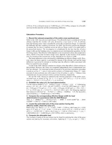
We use the AISC Manual to determine the relevant properties of the entire cross-
2
sectional area, as shown in Fig. 24: A 3.13 sq.in. (20.2 cm ); y b 5.23 in. (132.8
4
4
3
mm); I x 26.8 in (1115.5 cm ); R /16 in. (4.8 mm).
2. Establish the value of f c for load determination
0.5
2
0.5
Use the relation (8040t /f c ){1 – 2010/[( f c g)/t]} (H/D)( f c + f b )/f c – A
. Substituting
gives g B – 2(t + R) 12.0 – 2(0.105 + 0.1875) 11.415 in. (289.9 mm); g/t 108.7;
2
gt 1.20 sq.in. (7.74 cm ); A 3.13 – 1.20 1.93 sq.in. (12.45 cm ); y t 8.0 – 5.23
2
3
3
2.77 in. (70.36 cm); H 3.13(2.77) 8.670 in (142.1 cm ). The foregoing equation
0.5
0.5
then reduces to (88.64/f c )(1 – 18.49/f c ) 1.084( f c + 20,000)/f c – 1.93. By successive
approximations, f c 14,800 lb/sq.in. (102.0 MPa).
3. Compute the corresponding effective flange width for load
determination in accordance with the AISC Manual
0.5
0.5
0.5
Thus, b (8040t/f c )1 – 2010/[( f c g)/t] (8040 0.105/14,800 )[1 – 2010/
(14,800 0.5 108.7)] 5.885 in. (149.5 mm).
4. Locate the centroidal axis of the cross section having this
effective width; check the value of f c
Refer to Fig. 24b. Thus h g – b 11.415 – 5.885 5.530 in. (140.5 mm); ht 0.581
2
2
3
sq.in. (3.75 cm ); A 3.13 – 0.581 2.549 sq.in. (16.45 cm ); H 8.670 in (142.1
3
cm ); y t 8.670/2.549 3.40 in. (86.4 mm); y b 4.60 in. (116.8 mm); f c y t /y b
3.40(20,000)/4.60 14,800 lb/sq.in. (102.0 MPa), which is satisfactory.
5. Compute the allowable load
The moment of inertia of the net section may be found by applying the value of the gross
section and making the necessary corrections. Applying S x I x /y b , we get I x 26.8 +