Page 211 - Handbook of Civil Engineering Calculations, Second Edition
P. 211

1.194           STRUCTURAL STEEL ENGINEERING AND DESIGN


                              FIGURE 21. Bending-moment diagrams.


                                      2
                                               3
                               19.25(12) /[3(29)(10) ]   0.382 in. (9.7 mm). For dimensional homogeneity, the left
                            side of Eq. 5 must be multiplied by 1 kip (4.45 kN). The product represents the external
                            work performed by the unit loads.
                            REDUCTION IN WIND DRIFT BY USING
                            DIAGONAL BRACING

                            With reference to the previous calculation procedure, assume that the wind drift of the
                            bent is to be restricted to 0.20 in. (5.1 mm) by introducing diagonal bracing between lines
                            B and C. Design the bracing, using the gross area of the member.


                            Calculation Procedure:
                            1. State the change in length of the brace
                            The bent will be reinforced against lateral deflection by a pair of diagonal cross braces,
                            each brace being assumed to act solely as a tension member. Select the lightest single-
                            angle member that will satisfy the stiffness requirements; then compute the wind drift of
                            the reinforced bent.
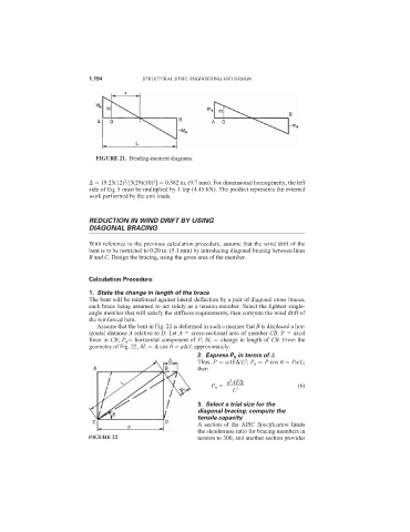
                              Assume that the bent in Fig. 22 is deformed in such a manner that B is displaced a hor-
                            izontal distance A relative to D. Let A   cross-sectional area of member CB; P   axial
                            force in CB; P h   horizontal component of P;  L   change in length of CB. From the
                            geometry of Fig. 22,  L    cos 	   a /L approximately.
                                                            2. Express P h in terms of
                                                            Thus, P   aAE /L ; P h   P cos 	   Pa/L;
                                                                          2
                                                            then
                                                                      2
                                                                     a AE
                                                                P h                       (6)
                                                                      L 3
                                                            3. Select a trial size for the
                                                            diagonal bracing; compute the
                                                            tensile capacity
                                                            A section of the AISC  Specification limits
                                                            the slenderness ratio for bracing members in
                           FIGURE 22                        tension to 300, and another section provides
   206   207   208   209   210   211   212   213   214   215   216