
Page 218 - Handbook of Civil Engineering Calculations, Second Edition
P. 218
REINFORCED CONCRETE 2.3
PART 1
REINFORCED CONCRETE
The design of reinforced-concrete members in this handbook is executed in accordance
with the specification titled Building Code Requirements for Reinforced Concrete of
the American Concrete Institute (ACI). The ACI Reinforced Concrete Design Hand-
book contains many useful tables that expedite design work. The designer should
become thoroughly familiar with this handbook and use the tables it contains whenever
possible.
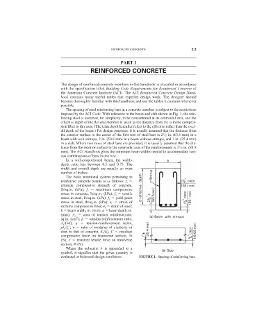
The spacing of steel reinforcing bars in a concrete member is subject to the restrictions
imposed by the ACI Code. With reference to the beam and slab shown in Fig. 1, the rein-
forcing steel is assumed, for simplicity, to be concentrated at its centroidal axis, and the
effective depth of the flexural member is taken as the distance from the extreme compres-
sion fiber to this axis. (The term depth hereafter refers to the effective rather than the over-
all depth of the beam.) For design purposes, it is usually assumed that the distance from
the exterior surface to the center of the first row of steel bars is 2 /2 in. (63.5 mm) in a
1
beam with web stirrups, 2 in. (50.8 mm) in a beam without stirrups, and 1 in. (25.4 mm)
in a slab. Where two rows of steel bars are provided, it is usually assumed that the dis-
1
tance from the exterior surface to the centroidal axis of the reinforcement is 3 /2 in. (88.9
mm). The ACI Handbook gives the minimum beam widths needed to accommodate vari-
ous combinations of bars in one row.
In a well-proportioned beam, the width-
depth ratio lies between 0.5 and 0.75. The
width and overall depth are usually an even
number of inches.
The basic notational system pertaining to
reinforced concrete beams is as follows: f
c
ultimate compressive strength of concrete,
lb/sq.in. (kPa); f c maximum compressive
stress in concrete, lb/sq.in. (kPa); f s tensile
stress in steel, lb/sq.in. (kPa); f y yield-point
stress in steel, lb/sq.in. (kPa);
c strain of
extreme compression fiber;
s strain of steel;
b beam width, in. (mm); d beam depth, in.
(mm); A s area of tension reinforcement,
2
sq.in. (cm ); p tension-reinforcement ratio,
A s /(bd); q tension-reinforcement index,
pf y /f c
; n ratio of modulus of elasticity of
steel to that of concrete, E s /E c ; C resultant
compressive force on transverse section, lb
(N); T resultant tensile force on transverse
section, lb (N).
Where the subscript b is appended to a
symbol, it signifies that the given quantity is
evaluated at balanced-design conditions. FIGURE 1. Spacing of reinforcing bars.