
Page 223 - Handbook of Civil Engineering Calculations, Second Edition
P. 223
2.8 REINFORCED AND PRESTRESSED CONCRETE ENGINEERING AND DESIGN
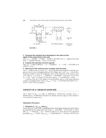
FIGURE 4
2. Compute the resultant force developed in the web and the
depth of the stress block in the web
Thus, C uw 328,000 275,400 52,600 lb (233,964.8 N); m depth of the stress
block 52,600/[2550(10)] 2.06 in. (52.324 mm).
3. Evaluate the ultimate-moment capacity
Thus, M u 0.90[275,400(20.5 3) 52,600(20.5 6 1.03)] 4,975,000 in.·lb
(562,075.5 N·m).
4. Determine if the reinforcement complies with the Code
Let b
width of web, in. (mm); A s1 area of reinforcement needed to resist the com-
2
pressive force in the overhanging portion of the flange, sq.in. (cm ); A s2 area of rein-
forcement needed to resist the compressive force in the remainder of the section, sq.in.
2
2
(cm ). Then p 2 A s2 /(b
d); A s1 2550(6)(18 10)740,000 3.06 sq.in. (19.743 cm );
A s2 8.20 3.06 5.14 sq.in. (33.163 cm ). Then p 2 5.14/[10(20.5)] 0.025.
2
A section of the ACI Code subjects the reinforcement ratio p 2 to the same restriction
as that in a rectangular beam. By Eq. 8, p 2,max 0.75p b 0.75(0.85)(0.85)(3/40)(87/127)
0.0278 > 0.025. This is acceptable.
CAPACITY OF A T BEAM OF GIVEN SIZE
The T beam in Fig. 5 is made of 3000-lb/sq.in. (20,685-kPa) concrete, and f y
40,000 lb/sq.in. (275,800 kPa). Determine the ultimate-moment capacity of this member if
it is reinforced in tension only.
Calculation Procedure:
1. Compute C u1 , C u2,max , and s max
Let the subscript 1 refer to the overhanging portion of the flange and the subscript 2 refer to
the remainder of the compression zone. Then f c 0.85(3000) 2550 lb/sq.in. (17,582.3
kPa); C u1 2550(5)(16 10) 76,500 lb (340,272 N). From the previous calculation
2
procedure, p 2,max 0.0278. Then A s2,max 0.0278(10)(19.5) 5.42 sq.in. (34.970 cm );