
Page 227 - Handbook of Civil Engineering Calculations, Second Edition
P. 227
2.12 REINFORCED AND PRESTRESSED CONCRETE ENGINEERING AND DESIGN
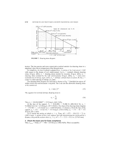
FIGURE 7. Shearing stress diagram.
tension. The less precise and more conservative method restricts the shearing stress to a
stipulated value that is independent of the flexural stress.
For simplicity, the latter method is adopted here. A section of the Code sets 0.85
with respect to the design of web reinforcement. Let v u nominal ultimate shearing
stress, lb/sq.in. (kPa); v c shearing stress resisted by concrete, lb/sq.in. (kPa); v u
shearing stress resisted by the web reinforcement, lb/sq.in. (kPa); A v total cross-
sectional area of stirrup, sq.in. (cm ); V u ultimate vertical shear at section, lb (N); s
2
center-to-center spacing of stirrups, in. (mm).
The shearing-stress diagram for half-span is shown in Fig. 7. Establish the region AF
within which web reinforcement is required. The Code sets the allowable shearing stress
in the concrete at
v c 2 ( f c
) 0.5 (15)
The equation for nominal ultimate shearing stress is
V u
v u (16)
bd
Then, v c 2(0.85)(3000) 0.5 93 lb/sq.in. (641.2 kPa).
At the face of the support, V u 9(10,200) 91,800 lb (408,326.4 N); v u
91,800/[15(22.5)] 272 lb/sq.in. (1875.44 kPa). The slope of the shearing-stress diagram
2
272/108 2.52 lb/(in ·in.) ( 0.684 kPa/mm). At distance d from the face of the
support, v u 272 22.5(2.52) 215 lb/sq.in. (1482.4 kPa); v u
215 93 122
lb/sq.in. (841.2 kPa).
Let E denote the section at which v u v c . Then, AE (272 93)/2.52 71 in.
(1803.4 mm). A section of the Code requires that web reinforcement be continued for a
distance d beyond the section where v u v c ; AF 71 22.5 93.5 in. (2374.9 mm).
2. Check the beam size for Code compliance
Thus, v u,max 10 ( f c
) 0.5 466 > 215 lb/sq.in. (1482.4 kPa). This is acceptable.