
Page 230 - Handbook of Civil Engineering Calculations, Second Edition
P. 230
REINFORCED CONCRETE 2.15
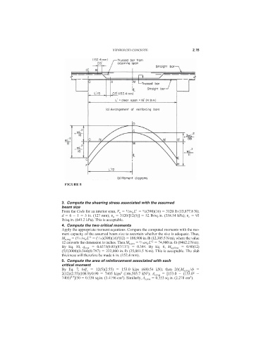
FIGURE 8
3. Compute the shearing stress associated with the assumed
beam size
1
From the Code for an interior span, V u /2w u L
/2(390)(16) 3120 lb (13,877.8 N);
1
d 6 1 5 in. (127 mm); v u 3120/[12(5)] 52 lb/sq.in. (358.54 kPa); v c 93
lb/sq.in. (641.2 kPa). This is acceptable.
4. Compute the two critical moments
Apply the appropriate moment equations. Compare the computed moments with the mo-
ment capacity of the assumed beam size to ascertain whether the size is adequate. Thus,
2
2
M u,neg ( /11/w u L
( /11)(390)(16) (12) 108,900 in.·lb (12,305.5 N·m), where the value
1
1
2
12 converts the dimension to inches. Then M u,pos /16w u L
74,900 in.·lb (8462.2 N·m).
1
By Eq. 10, q max 0.6375(0.85)(87/137) 0.344. By Eq. 6, M u,allow 0.90(12)
2
(5) (3000)(0.344)(0.797) 222,000 in.·lb (25,081.5 N·m). This is acceptable. The slab
thickness will therefore be made 6 in. (152.4 mm).
5. Compute the area of reinforcement associated with each
critical moment
By Eq. 7, bdf c 12(5)(2.55) 153.0 kips (680.54 kN); then 2bf c M u,neg /
2
2(12)(2.55)(108.9)/0.90 7405 kips (146,505.7 kN ); A s,neg [153.0 (153.0
2
2
2
2
0.5
7405) ]/50 0.530 sq.in. (3.4196 cm ). Similarly, A s,pos 0.353 sq.in. (2.278 cm ).