Page 233 - Handbook of Civil Engineering Calculations, Second Edition
P. 233

2.18    REINFORCED AND PRESTRESSED CONCRETE ENGINEERING AND DESIGN


                            the supports rotate as planes. Refer to Fig. 9b and c: 	 1   /6; 	 2   2	 1   /3   0.333 ;
                            	 3   /b; 	 4   /c; 	 5   (1/b   1/c)   [ /(AE)](6/a   a/6).
                            3. Select a trial value of a, and evaluate the distances and angles
                                                                        2
                                                                            2 0.5
                            Using a   4.5 ft (1.37 m) as the trial value, we find AE   (a   6 )    7.5 ft (2.28 m);
                            b   5.63 ft (1.716 m); c   10 ft (3.0 m); 	 5   ( /7.5)(6/4.5   4.5/6)   0.278 .
                            4. Develop an equation for the external work W E performed by the
                            uniform load on a surface that rotates about a horizontal axis
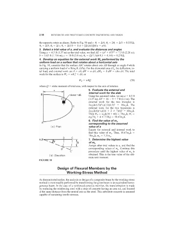
                            In Fig. 10, consider that the surface ABC rotates about axis AB through an angle 	 while
                            carrying a uniform load of w lb/sq.ft. (kPa). For the elemental area dA s , the deflection, to-
                            tal load, and external work are     x	; dW   wdA; dW E     dW   x	wdA. The total
                            work for the surface is W E   w	     dA, or
                                                      W E   w	Q                          (20)

                            where Q   static moment of total area, with respect to the axis of rotation.
                                                             5. Evaluate the external and
                                                             internal work for the slab
                                                             Using the assumed value, we see a   4.5 ft
                                                             (1.37 m), EF   16   9   7 ft (2.1 m). The
                                                             external work for the two triangles is
                                                             2w u ( /4.5)( /6)(12)(4.5) 2    18w u  . The
                                                                     1
                                                             external work for the two trapezoids is
                                                                                   2
                                                                    1
                                                             2w u ( /6)( /6)(16   2   7)(6)   60w u  .
                                                             Then W E   w u  (18   60)   78w u  ; W I
                                                             m u (7	 2   4   7.5	 5 )   10.67m u  .
                                                             6. Find the value of m u
                                                             corresponding to the assumed
                                                             value of a
                                                             Equate the external and internal work to
                                                             find this value of  m u . Thus, 10.67m u
                                                             78w u  ; m u   7.31w u .
                                                             7. Determine the highest value
                                                             of m u
                                                             Assign other trial values to a, and find the
                                                             corresponding values of m u . Continue this
                                                             procedure until the highest value of m u is
                                                             obtained. This is the true value of the ulti-
                                                             mate unit moment.
                           FIGURE 10

                                        Design of Flexural Members by the
                                              Working-Stress Method

                            As demonstrated earlier, the analysis or design of a composite beam by the working-stress
                            method is most readily performed by transforming the given beam to an equivalent homo-
                            geneous beam. In the case of a reinforced-concrete member, the transformation is made
                            by replacing the reinforcing steel with a strip of concrete having an area nA s and located
                            at the same distance from the neutral axis as the steel. This substitute concrete is assumed
                            capable of sustaining tensile stresses.
   228   229   230   231   232   233   234   235   236   237   238