
Page 235 - Handbook of Civil Engineering Calculations, Second Edition
P. 235
2.20 REINFORCED AND PRESTRESSED CONCRETE ENGINEERING AND DESIGN
TABLE 1. Values of Design Parameters at Balanced Design
f c
and n f c f s K k j p
2500 1125 20,000 178 0.360 0.880 0.0101
0010
3000 1350 20,000 223 0.378 0.874 0.0128
0009
4000 1800 20,000 324 0.419 0.853 0.0188
0008
5000 2250 20,000 423 0.441 0.853 0.0248
0007
stress is said to be in balanced design.
For each set of values of f c
and f s , there
is a corresponding set of values of K, k, j,
and p associated with balanced design.
These values are recorded in Table 1.
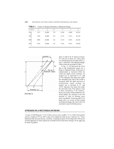
In Fig. 12, AB represents the stress
line of the transformed section for a
beam in balanced design. If the area of
reinforcement is increased while the
width and depth remain constant, the
neutral axis is depressed to O
, and
A
O
B represents the stress line under
the allowable load. But if the width is
increased while the depth and area of
reinforcement remain constant, the
neutral axis is elevated to O , and
AO B
represents the stress line under
the allowable load. This analysis leads
to these conclusions: If the reinforce-
ment is in excess of that needed for bal-
FIGURE 12
anced design, the concrete is the first
material to reach its limiting stress
under a gradually increasing load. If the
beam size is in excess of that needed
for balanced design, the steel is the first
material to reach its limiting stress.
STRESSES IN A RECTANGULAR BEAM
A beam of 2500-lb/sq.in (17,237.5-kPa) concrete has a width of 12 in. (304.8 mm) and an
effective depth of 19.5 in. (495.3 mm). It is reinforced with one no. 9 and two no. 7 bars.
Determine the flexural stresses caused by a bending moment of 62 ft·kips (84.1 kN·m) (a)
without applying the basic equations of reinforced-concrete beam design; (b) by applying
the basic equations.