Page 234 - Handbook of Civil Engineering Calculations, Second Edition
P. 234

REINFORCED CONCRETE                  2.19

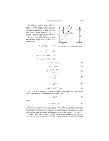
                                The following symbols, shown in Fig. 11,
                              are to be added to the notational system given
                              earlier: kd   distance from extreme compres-
                              sion fiber to neutral axis, in. (mm); jd   dis-
                              tance between action lines of  C and  T, in.
                              (mm); z   distance from extreme compression
                              fiber to action line of C, in. (mm).
                                The basic equations for the working-stress
                              design of a rectangular beam reinforced solely
                              in tension are

                                                   f c
                                             k              (21)
                                                f c   f s /n      FIGURE 11. Stress and resultant forces.
                                                     k
                                              j   1         (22)
                                                     3
                                          M   Cjd   /2f c kjbd  2  (23)
                                                   1
                                          M   /6f c k(3   k)bd  2  (24)
                                              1
                                                      M   Tjd   f s A s jd                 (25)
                                                        M   f s pjbd  2                    (26)
                                                           2
                                                          f s k (3   k)bd  2
                                                     M                                     (27)
                                                           6n(1   k)
                                                             f c k
                                                          p                                (28)
                                                             2f s
                                                              k 2
                                                       p                                   (29)
                                                            2n(1
                                                              k)
                                                               2 0.5
                                                   k   [2pn   (pn) ]    pn                 (30)
                                For a given set of values of f c , f s , and n, M is directly proportional to the beam proper-
                                  2
                              ty bd . Let K denote the constant of proportionality. Then
                                                         M   Kbd  2                        (31)
                              where
                                                      K   /2f c kj   f s pj                (32)
                                                          1
                                The allowable flexural stress in the concrete and the value of n, which are functions of
                              the ultimate strength f c 
, are given in the ACI Code, as is the allowable flexural stress in the
                              steel. In all instances in the following procedures, the assumption is that the reinforcement
                              is intermediate-grade steel having an allowable stress of 20,000 lb/sq.in. (137,900 kPa).
                                Consider that the load on a beam is gradually increased until a limiting stress is induced. A
                              beam that is so proportioned that the steel and concrete simultaneously attain their limiting
   229   230   231   232   233   234   235   236   237   238   239