
Page 240 - Handbook of Civil Engineering Calculations, Second Edition
P. 240
REINFORCED CONCRETE 2.25
Using f c
3000 lb/sq.in. (20,685 kPa) and an allowable stress f v in the stirrups of 20,000
lb/sq.in. (137,900 kPa), design web reinforcement in the form of vertical U stirrups.
Calculation Procedure:
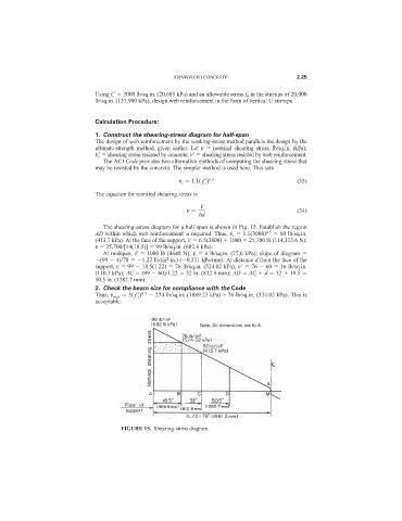
1. Construct the shearing-stress diagram for half-span
The design of web reinforcement by the working-stress method parallels the design by the
ultimate-strength method, given earlier. Let v nominal shearing stress, lb/sq.in. (kPa);
v c
shearing stress resisted by concrete; v
shearing stress resisted by web reinforcement.
The ACI Code provides two alternative methods of computing the shearing stress that
may be resisted by the concrete. The simpler method is used here. This sets
v c 1.1( f c
) 0.5 (33)
The equation for nominal shearing stress is
V
v (34)
bd
The shearing-stress diagram for a half-span is shown in Fig. 15. Establish the region
AD within which web reinforcement is required. Thus, v c 1.1(3000) 0.5 60 lb/sq.in.
(413.7 kPa). At the face of the support, V 6.5(3800) 1000 25,700 lb (114,313.6 N);
v 25,700/[14(18.5)] 99 lb/sq.in. (682.6 kPa).
At midspan, V 1000 lb (4448 N); v 4 lb/sq.in. (27.6 kPa); slope of diagram
2
(99 4)/78 1.22 lb/(in ·in.) ( 0.331 kPa/mm). At distance d from the face of the
support, v 99 18.5(1.22) 76 lb/sq.in. (524.02 kPa); v
76 60 16 lb/sq.in.
(110.3 kPa); AC (99 60)/1.22 32 in. (812.8 mm); AD AC d 32 18.5
50.5 in. (1282.7 mm).
2. Check the beam size for compliance with the Code
Thus, v max 5( f c
) 0.5 274 lb/sq.in. (1889.23 kPa) > 76 lb/sq.in. (524.02 kPa). This is
acceptable.
FIGURE 15. Shearing-stress diagram.