
Page 241 - Handbook of Civil Engineering Calculations, Second Edition
P. 241
2.26 REINFORCED AND PRESTRESSED CONCRETE ENGINEERING AND DESIGN
3. Select the stirrup size
Use the method given earlier in the ultimate-strength calculation procedure to select the
stirrup size, establish the maximum allowable spacing, and devise a satisfactory spacing.
CAPACITY OF A T BEAM
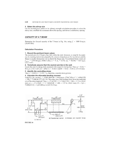
Determine the flexural capacity of the T beam in Fig. 16a, using f c
3000 lb/sq.in.
(20,685 kPa).
Calculation Procedure:
1. Record the pertinent beam values
The neutral axis of a T beam often falls within the web. However, to simplify the analy-
sis, the resisting moment developed by the concrete lying between the neutral axis and the
flange is usually disregarded. Let A f denote the flange area. The pertinent beam values are
f c,allow 1350 lb/sq.in. (9308.3 kPa); n 9; k b 0.378; nA s 9(4.00) 36.0 sq.in.
2
(232.3 cm ).
2. Tentatively assume that the neutral axis lies in the web
Locate this axis by taking static moments with respect to the top line. Thus A f 5(16)
2
80 sq.in. (516.2 cm ); kd [80(2.5) 36.0(21.5)]/(80 36.0) 8.40 in. (213.36 mm).
3. Identify the controlling stress
Thus k 8.40/21.5 0.391 > k b ; therefore, concrete stress governs.
4. Calculate the allowable bending moment
1
Using Fig. 16c, we see f c1 1350(3.40)/8.40 546 lb/sq.in. (3764.7 kPa); C /2(80)(1350
546) 75,800 lb (337,158.4 N). The action line of this resultant force lies at the centroidal
axis of the stress trapezoid. Thus, z ( /3)(1350 2 546)/(1350 546) 2.15 in. (54.61
5
mm); or z ( /3) (8.40 2 3.40)/(8.40 3.40) 2.15 in. (54.61 mm); M Cjd
5
75,800(19.35) 1,467,000 in.·lb (165,741 N·m).
FIGURE 16