Page 243 - Handbook of Civil Engineering Calculations, Second Edition
P. 243

2.28    REINFORCED AND PRESTRESSED CONCRETE ENGINEERING AND DESIGN

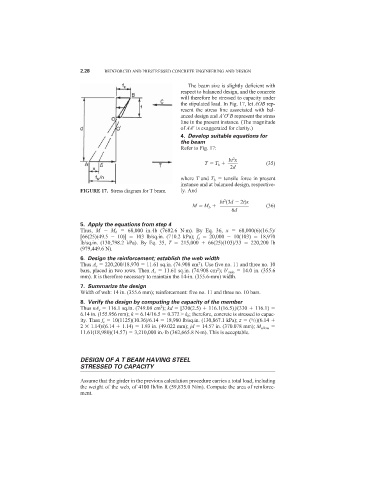
                                                               The beam size is slightly deficient with
                                                             respect to balanced design, and the concrete
                                                             will therefore be stressed to capacity under
                                                             the stipulated load. In Fig. 17, let AOB rep-
                                                             resent the stress line associated with bal-
                                                             anced design and A
O
B represent the stress
                                                             line in the present instance. (The magnitude
                                                             of AA
 is exaggerated for clarity.)
                                                             4. Develop suitable equations for
                                                             the beam
                                                             Refer to Fig. 17:
                                                                              2
                                                                             bt x
                                                                     T   T b             (35)
                                                                             2d
                                                             where T and T b   tensile force in present
                                                             instance and at balanced design, respective-
                            FIGURE 17. Stress diagram for T beam.  ly. And
                                                                           2
                                                                          bt (3d   2t)x
                                                                 M   M b                 (36)
                                                                              6d
                            5. Apply the equations from step 4
                            Thus, M    M b   68,000 in.·lb (7682.6 N·m). By Eq. 36,  x   68,000(6)(16.5)/
                            [66(25)(49.5    10)]    103 lb/sq.in. (710.2 kPa);  f s   20,000    10(103)    18,970
                            lb/sq.in. (130,798.2 kPa). By Eq. 35,  T   215,000    66(25)(103)/33    220,200 lb
                            (979,449.6 N).
                            6. Design the reinforcement; establish the web width
                                                                   2
                            Thus A s   220,200/18,970   11.61 sq.in. (74.908 cm ). Use five no. 11 and three no. 10
                                                                         2
                            bars, placed in two rows. Then A s   11.61 sq.in. (74.908 cm ); b
 min   14.0 in. (355.6
                            mm). It is therefore necessary to maintain the 14-in. (355.6-mm) width.
                            7. Summarize the design
                            Width of web: 14 in. (355.6 mm); reinforcement: five no. 11 and three no. 10 bars.
                            8. Verify the design by computing the capacity of the member
                            Thus nA s   116.1 sq.in. (749.08 cm ); kd   [330(2.5)   116.1(16.5)]/(330   116.1)
                                                      2
                            6.14 in. (155.956 mm); k   6.14/16.5   0.372 > k b ; therefore, concrete is stressed to capac-
                            ity. Then f s   10(1125)(10.36)/6.14   18,980 lb/sq.in. (130,867.1 kPa); z   ( /3)(6.14
                                                                                    5
                            2   1.14)/(6.14   1.14)   1.93 in. (49.022 mm); jd   14.57 in. (370.078 mm); M allow
                            11.61(18,980)(14.57)   3,210,000 in.·lb (362,665.8 N·m). This is acceptable.


                            DESIGN OF A T BEAM HAVING STEEL
                            STRESSED TO CAPACITY

                            Assume that the girder in the previous calculation procedure carries a total load, including
                            the weight of the web, of 4100 lb/lin ft (59,835.0 N/m). Compute the area of reinforce-
                            ment.
   238   239   240   241   242   243   244   245   246   247   248