
Page 248 - Handbook of Civil Engineering Calculations, Second Edition
P. 248
REINFORCED CONCRETE 2.33
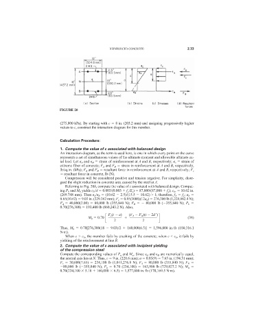
FIGURE 20
(275,800 kPa). By starting with c 8 in. (203.2 mm) and assigning progressively higher
values to c, construct the interaction diagram for this member.
Calculation Procedure:
1. Compute the value of c associated with balanced design
An interaction diagram, as the term is used here, is one in which every point on the curve
represents a set of simultaneous values of the ultimate moment and allowable ultimate ax-
ial load. Let
A and
B strain of reinforcement at A and B, respectively;
c strain of
extreme fiber of concrete; F A and F B stress in reinforcement at A and B, respectively,
lb/sq.in. (kPa); F A and F B resultant force in reinforcement at A and B, respectively; F c
resultant force in concrete, lb (N).
Compression will be considered positive and tension negative. For simplicity, disre-
gard the slight reduction in concrete area caused by the steel at A.
Referring to Fig. 20b, compute the value of c associated with balanced design. Comput-
ing P b and M b yields c b /d 0.003/(0.003 f y /E s ) 87,000/(87,000 f y ); c b , 10.62 in.
(269.748 mm). Then
A /
B (10.62 2.5)/(15.5 10.62) > 1; therefore, f A f y ; a b
0.85(10.62) 9.03 in. (229.362 mm); F c 0.85(3000)(12a b ) 276,300 lb (1,228,982.4 N);
F A 40,000(2.00) 80,000 lb (355,840 N); F B 80,000 lb ( 355,840 N); P b
0.70(276,300) 193,400 lb (860,243.2 N). Also,
F c (t a) (F A F B )(t 2d
)
M b 0.70 (38)
2
2
Thus, M b 0.70[276,300(18 9.03)/2 160,000(6.5)] 1,596,000 in.·lb (180,316.1
N·m).
When c > c b , the member fails by crushing of the concrete; when c < c b , it fails by
yielding of the reinforcement at line B.
2. Compute the value of c associated with incipient yielding
of the compression steel
Compute the corresponding values of P u and M u . Since
A and
B are numerically equal,
the neutral axis lies at N. Thus, c 9 in. (228.6 mm); a 0.85(9) 7.65 in. (194.31 mm);
F c 30,600(7.65) 234,100 lb (1,041,276.8 N); F A 80,000 lb (355,840 N); F B
80,000 lb ( 355,840 N); P u 0.70 (234,100) 163,900 lb (729,027.2 N); M u
0.70(234,100 5.18 160,000 6.5) 1,577,000 in.·lb (178,169.5 N·m).