Page 253 - Handbook of Civil Engineering Calculations, Second Edition
P. 253

2.38    REINFORCED AND PRESTRESSED CONCRETE ENGINEERING AND DESIGN

                            ANALYSIS OF A RECTANGULAR MEMBER BY
                            INTERACTION DIAGRAM

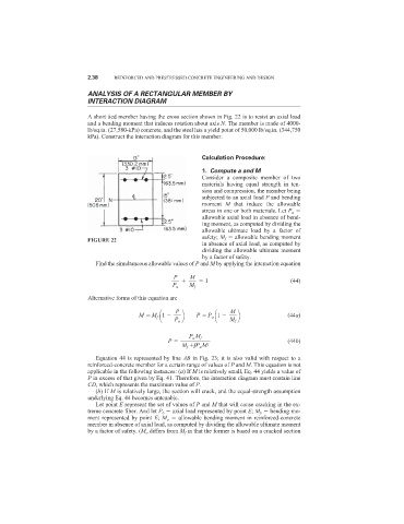
                            A short tied member having the cross section shown in Fig. 22 is to resist an axial load
                            and a bending moment that induces rotation about axis N. The member is made of 4000-
                            lb/sq.in. (27,580-kPa) concrete, and the steel has a yield point of 50,000 lb/sq.in. (344,750
                            kPa). Construct the interaction diagram for this member.


                                                              Calculation Procedure:

                                                              1. Compute a and M
                                                              Consider a composite member of two
                                                              materials having equal strength in ten-
                                                              sion and compression, the member being
                                                              subjected to an axial load P and bending
                                                              moment  M that induce the allowable
                                                              stress in one or both materials. Let P a
                                                              allowable axial load in absence of bend-
                                                              ing moment, as computed by dividing the
                                                              allowable ultimate load by a factor of
                                                              safety; M f   allowable bending moment
                            FIGURE 22
                                                              in absence of axial load, as computed by
                                                              dividing the allowable ultimate moment
                                                              by a factor of safety.
                              Find the simultaneous allowable values of P and M by applying the interaction equation

                                                      P   M
                                                               1                         (44)
                                                     P a  M f
                            Alternative forms of this equation are
                                                 
    P           
    M
                                           M   M f 1        P   P a  1                  (44a)
                                                      P a
                                                                       M f

                                                          P a M f
                                                    P                                   (44b)
                                                        M f   P a M/
                                                            P
                              Equation 44 is represented by line AB in Fig. 23; it is also valid with respect to a
                            reinforced-concrete member for a certain range of values of P and M. This equation is not
                            applicable in the following instances: (a) If M is relatively small, Eq. 44 yields a value of
                            P in excess of that given by Eq. 41. Therefore, the interaction diagram must contain line
                            CD, which represents the maximum value of P.
                              (b) If M is relatively large, the section will crack, and the equal-strength assumption
                            underlying Eq. 44 becomes untenable.
                              Let point E represent the set of values of P and M that will cause cracking in the ex-
                            treme concrete fiber. And let P b   axial load represented by point E; M b   bending mo-
                            ment represented by point E; M o   allowable bending moment in reinforced-concrete
                            member in absence of axial load, as computed by dividing the allowable ultimate moment
                            by a factor of safety. (M o differs from M f in that the former is based on a cracked section
   248   249   250   251   252   253   254   255   256   257   258