
Page 258 - Handbook of Civil Engineering Calculations, Second Edition
P. 258
REINFORCED CONCRETE 2.43
7. Design the reinforcement
In Fig. 24, EA 3.00 ft (0.914 m); V EF 380(3.00/7.67) 148.6 kips (666.97 kN); M EF
1
148.6( /2)(3.00)(12) 2675 in.·kips (302.22 kN·m); A s 2675/[20(0.874)(19.5)] 7.85 sq.in.
2
2
(50.648 cm ). Try 10 no. 8 bars each way. Then A s 7.90 sq.in. (50.971 cm ); o 31.4 in.
(797.56 mm); u V EF / ojd 148,600/[31.4(0.874)(19.5)] 278 lb/sq.in. (1916.81 kPa);
u allow 264/1 264 lb/sq.in. (1820.3 kPa).
The bond stress at EF is slightly excessive. However, the ACI Code, in sections based
on ultimate-strength considerations, permits disregarding the local bond stress if the aver-
age bond stress across the length of embedment is less than 80 percent of the allowable
stress. Let L e denote this length. Then L e EA 3 33 in. (838.2 mm); 0.80u allow
211 lb/sq.in. (1454.8 kPa); u av A s f s /(L e o) 0.79(20,000)/[33(3.1)] 154 lb/sq.in.
(1061.8 kPa). This is acceptable.
8. Design the dowels to comply with the Code
The function of the dowels is to transfer the compressive force in the column reinforcing
bars to the footing. Since this is a tied column, assume the stress in the bars is 0.85(20,000)
17,000 lb/sq.in. (117,215.0 kPa). Try eight no. 9 dowels with f y 40,000 lb/sq.in.
(275,800.0 kPa). Then u 264/(9/8) 235 lb/sq.in. (1620.3 kPa); L e 1.00(17,000)/
[235(3.5)] 20.7 in. (525.78 mm). Since
the footing can provide a 21-in. (533.4-
mm) embedment length, the dowel selec-
tion is satisfactory. Also, the length of
lap 20(9/8) 22.5 in. (571.5 mm);
length of dowels 20.7 22.5 43.2,
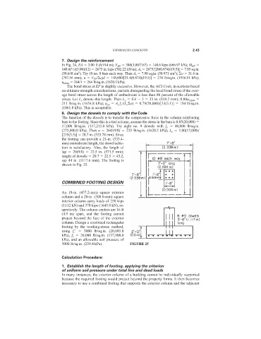
say 44 in. (1117.6 mm). The footing is
shown in Fig. 25.
COMBINED FOOTING DESIGN
An 18-in. (457.2-mm) square exterior
column and a 20-in. (508.0-mm) square
interior column carry loads of 250 kips
(1112 kN) and 370 kips (1645.8 kN), re-
spectively. The column centers are 16 ft
(4.9 m) apart, and the footing cannot
project beyond the face of the exterior
column. Design a combined rectangular
footing by the working-stress method,
using f c
3000 lb/sq.in. (20,685.0
kPa), f s 20,000 lb/sq.in. (137,900.0
kPa), and an allowable soil pressure of
5000 lb/sq.in. (239.4 kPa). FIGURE 25
Calculation Procedure:
1. Establish the length of footing, applying the criterion
of uniform soil pressure under total live and dead loads
In many instances, the exterior column of a building cannot be individually supported
because the required footing would project beyond the property limits. It then becomes
necessary to use a combined footing that supports the exterior column and the adjacent