
Page 260 - Handbook of Civil Engineering Calculations, Second Edition
P. 260
REINFORCED CONCRETE 2.45
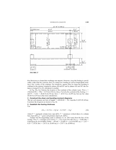
FIGURE 27
thus functions as a beam that overhangs one support. However, since the footing is consid-
erably wider than the columns, there is a transverse bending as well as longitudinal bend-
ing in the vicinity of the columns. For simplicity, assume that the transverse bending is
confined to the regions bounded by planes AB and EF and by planes GH and NP, the dis-
tance m being h/2 or d/2, whichever is smaller.
In Fig. 26a, let Z denote the location of the resultant of the column loads. Then x
370(16)/(250 370) 9.55 ft (2.910 m). Since Z is to be the centroid of the footing, L
2(0.75 9.55) 20.60 ft (6.278 m). Set L 20 ft 8 in. (6.299 m), but use the value
20.60 ft (6.278 m) in the stress calculations.
2. Construct the shear and bending-moment diagrams
The net soil pressure per foot of length 620/20.60 30.1 kips/lin ft (439.28 kN/m).
Construct the diagrams as shown in Fig. 26.
3. Establish the footing thickness
Use
2
(Pv 2 0.17VL Pp
)d 0.17Pd VLp
(50)
where P aggregate column load, kips (kN); V maximum vertical shear at a column
face, kips (kN); p
gross soil pressure, kips/sq.ft. (MPa).
Assume that the longitudinal steel is centered 3 /2 in. (88.9 mm) from the face of the
1
footing. Then P 620 kips (2757.8 kN); V 229.2 kips (1019.48 kN); v 2 0.06(144)
2
8.64 kips/sq.ft. (0.414 MPa); 9260d 105.4d 23,608; d 2.63 ft (0.801 m); t 2.63
0.29 2.92 ft. Set t 2 ft 11 in. (0.889 m); d 2 ft 7 /2 in. (0.800 m).
1