
Page 265 - Handbook of Civil Engineering Calculations, Second Edition
P. 265
2.50 REINFORCED AND PRESTRESSED CONCRETE ENGINEERING AND DESIGN
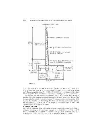
FIGURE 30
(3.531 m), where M 218,400 in.·lb (24,674.8 N·m); d 4.5 10(11.58/16.5)
11.52 in. (292.608 mm); A s 218,400/[20,000 (0.874)(11.52)] 1.08 sq.in. (6.968
2
cm ). This is acceptable. Also, T 3930 lb (17,480.6 N); u 101 lb/sq.in. (696.4 kPa).
This is acceptable. From the ACI Code, anchorage 12(9/8) 13.5 in. (342.9 mm).
The alternate bars will therefore be terminated at 6 ft 1 in. (1.854 m) above the top of
the base. The Code requires that special precautions be taken where more than half the
bars are spliced at a point of maximum stress. To circumvent this requirement, the short
bars can be extended into the footing; therefore only the long bars require splicing.
For the dowels, u allow 0.75(235) 176 lb/sq.in. (1213.5 kPa); length of lap 1.00
(20,000)/[176(3.5)] 33 in. (838.2 mm).
5. Design the heel
Let V and M denote the shear and bending moment, respectively, at section D. Case 1:
surcharge extending to G—downward pressure p 16.5(130) 1.5(150) 2370
lb/sq.ft.(113.5 kPa); V 6.5[2370 /2(2244 171)] 7560 lb (33,626.9 N); M
1
1
12(6.5) [ /2 2370 /6(2244 2 171)] 383,000 in.·lb (43,271.3 N·m).
2 1