
Page 264 - Handbook of Civil Engineering Calculations, Second Edition
P. 264
REINFORCED CONCRETE 2.49
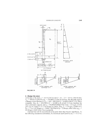
FIGURE 29
4. Design the stem
At the base of the stem, y 16.5 ft (5.03 m) and d 18 3.5 14.5 in. (368.30 mm);
T EF 7030 lb (31,269.4 N); M EF 538,000 in.·lb (60,783.24 N·m). The allowable shear at
a distance d above the base is V allow vbd 60(12)(14.5) 10,440 lb (46,437.1 N). This is
2
acceptable. Also, M b 223(12)(14.5) 563,000 in.·lb (63,607.74 N·m); therefore, the
steel is stressed to capacity, and A s 538,000/[20,000(0.874)(14.5)] 2.12 sq.in. (13.678
2
2
1
cm ). Use no. 9 bars 5 /2 in. (139.70 mm) on centers. Thus, A s 2.18 sq.in. (14.065 cm );
o 7.7 in. (195.58/mm); u 7030/[7.7(0.874)(14.5)] 72 lb/sq.in. (496.5 kPa); u allow
235 lb/sq.in. (1620.3 kPa). This is acceptable.
Alternate bars will be discontinued at the point where they become superfluous. As
the following calculations demonstrate, the theoretical cutoff point lies at y 11 ft 7 in.