
Page 259 - Handbook of Civil Engineering Calculations, Second Edition
P. 259
2.44 REINFORCED AND PRESTRESSED CONCRETE ENGINEERING AND DESIGN
FIGURE 26
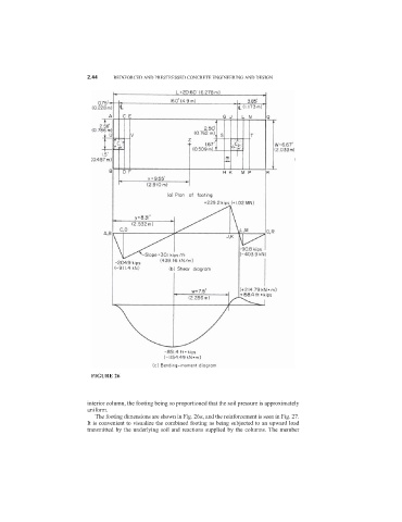
interior column, the footing being so proportioned that the soil pressure is approximately
uniform.
The footing dimensions are shown in Fig. 26a, and the reinforcement is seen in Fig. 27.
It is convenient to visualize the combined footing as being subjected to an upward load
transmitted by the underlying soil and reactions supplied by the columns. The member