
Page 262 - Handbook of Civil Engineering Calculations, Second Edition
P. 262
REINFORCED CONCRETE 2.47
comprises a vertical stem to retain the soil,
a horizontal base to support the stem, and in
many instances a key that projects into the
underlying soil to augment the resistance to
sliding. Adequate drainage is an essential
requirement, because the accumulation of
water or ice behind the wall would greatly
increase the horizontal thrust.
The calculation of earth thrust in this
section is based on Rankine’s theory, which
is developed in a later calculation proce-
dure. When a live load, termed a surcharge,
is applied to the retained soil, it is conven-
ient to replace this load with a hypothetical
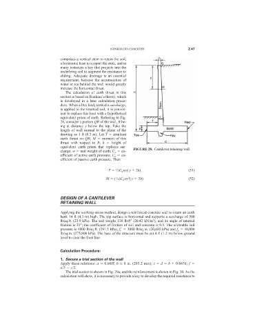
equivalent prism of earth. Referring to Fig.
28, consider a portion QR of the wall, R be-
ing at distance y below the top. Take the
length of wall normal to the plane of the
drawing as 1 ft (0.3 m). Let T resultant
earth thrust on QR; M moment of this
thrust with respect to R; h height of
equivalent earth prism that replaces sur-
charge; w unit weight of earth; C a co- FIGURE 28. Cantilever retaining wall.
efficient of active earth pressure; C p co-
efficient of passive earth pressure. Then
1
T /2C a wy( y 2h) (51)
2
M ( /6)C a wy ( y 3h) (52)
1
DESIGN OF A CANTILEVER
RETAINING WALL
Applying the working-stress method, design a reinforced-concrete wall to retain an earth
bank 14 ft (4.3 m) high. The top surface is horizontal and supports a surcharge of 500
3
3
lb/sq.ft. (23.9 kPa). The soil weighs 130 lb/ft (20.42 kN/m ), and its angle of internal
friction is 35°; the coefficient of friction of soil and concrete is 0.5. The allowable soil
pressure is 4000 lb/sq.ft. (191.5 kPa); f c
3000 lb/sq.in. (20,685 kPa) and f y 40,000
lb/sq.in. (275,800 kPa). The base of the structure must be set 4 ft (1.2 m) below ground
level to clear the frost line.
Calculation Procedure:
1. Secure a trial section of the wall
Apply these relations: a 0.60H; b 8 in. (203.2 mm); c d b 0.045h; f
a/3 c/2.
The trial section is shown in Fig. 29a, and the reinforcement is shown in Fig. 30. As the
calculation will show, it is necessary to provide a key to develop the required resistance to