
Page 263 - Handbook of Civil Engineering Calculations, Second Edition
P. 263
2.48 REINFORCED AND PRESTRESSED CONCRETE ENGINEERING AND DESIGN
sliding. The sides of the key are sloped to ensure that the surrounding soil will remain
undisturbed during excavation.
2. Analyze the trial section for stability
The requirements are that there be a factor of safety (FS) against sliding and overturning
of at least 1.5 and that the soil pressure have a value lying between 0 and 4000 lb/sq.ft.
(0 and 191.5 kPa). Using the equation developed later in this handbook gives h sur-
charge/soil weight 500/130 3.85 ft (1.173 m); sin 35° 0.574; tan 35° 0.700;
3
3
3
3
C a 0.271; C p 3.69; C a w 35.2 lb/ft (5.53 kN/m ); C p w 480 lb/ft (75.40 kN/m );
2
T AB /2(35.2)18(18 2 3.85) 8140 lb (36,206.7 N); M AB ( /6)35.2(18) (18 3
1
1
3.85) 56,200 ft·lb (76,207.2 N·m).
The critical condition with respect to stability is that in which the surcharge extends to
G. The moments of the stabilizing forces with respect to the toe are computed in Table 2. In
Fig. 29c, x 81,030/21,180 3.83 ft (1.167 m); e 5.50 3.83 1.67 ft (0.509 m). The
fact that the resultant strikes the base within the middle third attests to the absence of uplift.
By f (P/A)(1 ± 6e x /d x ±6e y /d y ), p a (21,180/11)(1 6 1.67/11) 3680 lb/sq.ft.
(176.2 kPa); p b (21,180/11)(1 6 1.67/11) 171 lb/sq.ft. (8.2 kPa). Check: x
(11/3)(3680 2 171)/(3680 171) 3.83 ft (1.167 m), as before. Also, p c 2723
lb/sq.ft. (130.4 kPa); p d 2244 lb/sq.ft. (107.4 kPa); FS against overturning
137,230/56,200 2.44. This is acceptable.
Lateral displacement of the wall produces sliding of earth on earth to the left of C and
of concrete on earth to the right of C. In calculating the passive pressure, the layer of earth
lying above the base is disregarded, since its effectiveness is unknown. The resistance to
1
sliding is as follows: friction, A to C (Fig. 29): /2(3680 2723)(3)(0.700) 6720 lb
1
(29,890.6 N); friction, C to B: /2(2723 171)(8)(0.5) 5790 lb (25,753.9 N); passive
2
earth pressure: /2(480)(2.75) 1820 lb (8095.4 N). The total resistance to sliding is the
1
sum of these three items, or 14,330 lb (63,739.8 N). Thus, the FS against sliding is
14,330/8140 1.76. This is acceptable because it exceeds 1.5. Hence the trial section is
adequate with respect to stability.
3. Calculate the soil pressures when the surcharge extends to H
Thus W s 500(6.5) 3250 lb (14,456 N); W 21,180 3250 24,430 lb (108,664.6
N); M a 81,030 3250(7.75) 106,220 ft·lb (144,034.3 N·m); x 106,220/24,430
4.35 ft (1.326 m); e 1.15 ft (0.351 m); p a 3613 lb/sq.ft. (173 kPa); p b 828 lb/sq.ft.
(39.6 kPa); p c 2853 lb/sq.ft. (136.6 kPa); p d 2474 lb/sq.ft. (118.5 kPa).
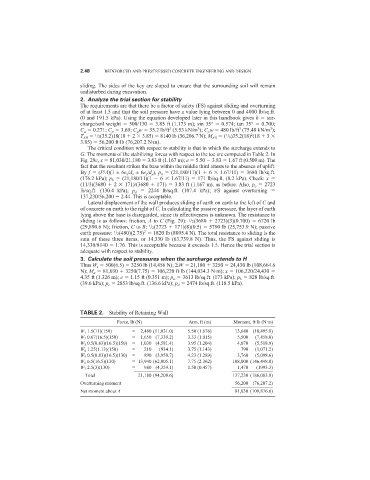
TABLE 2. Stability of Retaining Wall
Force, lb (N) Arm, ft (m) Moment, ft·lb (N·m)
W 1 1.5(11)(150) 2,480 (11,031.0) 5.50 (1.676) 13,640 (18,495.8)
W 2 0.67(16.5)(150) 1,650 (7,339.2) 3.33 (1.015) 5,500 (7,458.0)
W 3 0.5(0.83)(16.5)(150) 1,030 (4,581.4) 3.95 (1.204) 4,070 (5,518.9)
W 4 1.25(1.13)(150) 210 (934.1) 3.75 (1.143) 790 (1,071.2)
W 5 0.5(0.83)(16.5)(130) 890 (3,958.7) 4.23 (1.289) 3,760 (5,098.6)
W 6 6.5(16.5)(130) 13,940 (62,005.1) 7.75 (2.362) 108,000 (146,448.0)
1,470
(1993.3)
980 (4,359.1)
W 7 2.5(3)(130) ________________ 1.50 (0.457) _________________
Total 21,180 (94,208.6) 137,230 (186,083.8)
56,200 (76,207.2)
Overturning moment _________________
Net moment about A 81,030 (109,876.6)