
Page 256 - Handbook of Civil Engineering Calculations, Second Edition
P. 256
REINFORCED CONCRETE 2.41
Calculation Procedure:
1. Evaluate P when e = 10 in. (254 mm)
As the preceding calculations show, the eccentricity corresponding to point E in the inter-
action diagram is 8.03 in. (203.962 mm). Consequently, an eccentricity of 10 in. (254
mm) corresponds to a point on EF, and an eccentricity of 6 in. (152.4 mm) corresponds to
a point on ED.
By Eq. 45b, P 203(1140)7(1140 1630 203 10) 150 kips (667.2 kN).
2. Evaluate P when e = 6 in. (152.4 mm)
By Eq. 44b, P 506(2720)/(2720 506 6) 239 kips (1063.1 kN).
Design of Column Footings
A reinforced-concrete footing supporting a single column differs from the usual type of
flexural member in the following respects: It is subjected to bending in all directions, the
ratio of maximum vertical shear to maximum bending moment is very high, and it carries a
heavy load concentrated within a small area. The consequences are as follows: The footing
requires two-way reinforcement, its depth is determined by shearing rather than bending
stress, the punching-shear stress
below the column is usually more
critical than the shearing stress that
results from ordinary beam action,
and the design of the reinforce-
ment is controlled by the bond
stress as well as the bending stress.
Since the footing weight and
soil pressure are collinear, the for-
mer does not contribute to the ver-
tical shear or bending moment. It is
convenient to visualize the footing
as being subjected to an upward
load transmitted by the underlying
soil and a downward reaction sup-
plied by the column, this being, of
course, an inversion of the true
form of loading. The footing thus
functions as an overhanging beam.
The effective depth of footing is
taken as the distance from the top
surface to the center of the upper
row of bars, the two rows being
made identical to avoid confusion.
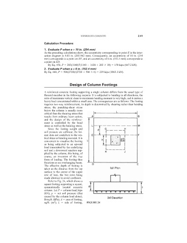
Refer to Fig. 24, which shows a
square footing supporting a square,
symmetrically located concrete
column. Let P column load, kips
(kN); p net soil pressure (that
caused by the column load alone),
lb/sq.ft. (kPa); A area of footing,
2
sq/ft. (m ); L side of footing, FIGURE 24