
Page 250 - Handbook of Civil Engineering Calculations, Second Edition
P. 250
REINFORCED CONCRETE 2.35
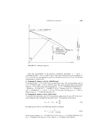
FIGURE 21. Interaction diagram.
From the computations of the previous calculation procedure, e b M b /P b
1,596,000/193,400 8.25 in. (209.55 mm). This result discloses that an eccentricity of
9.2 in. (233.68 mm) corresponds to a point on AB and an eccentricity of 6 in. (152.4 mm)
corresponds to a point on BC.
2. Evaluate P u when e = 9.2 in. (233.68 mm)
It was found that c 9 in. (228.6 mm) is a significant value. The corresponding value of
e is 1,577,000/163,900 9.62 in. (244.348 mm). This result discloses that in the present
instance c > 9 in. (228.6 mm) and consequently f A f y ; F A 80,000 lb (355,840 N); F B
80,000 lb ( 355,840 N); F c 30,600a; P u /0.70 30,600a; M u /0.70 30,600a(18
a)/2 160,000(6.5); e M u /P u 9.2 in. (233.68 mm). Solving gives a 8.05 in.
(204.47 mm), P u 172,400 lb (766,835.2 N).
3. Evaluate P u when e = 6 in. (152.4 mm)
To simplify this calculation, the ACI Code permits replacement of curve BC in the inter-
action diagram with a straight line through B and C. The equation of this line is
M u
P u P o (P o B b ) (39)
M b
By replacing M u with P u e, the following relation is obtained:
P o
P u (39a)
1 (P o P b )e/M b
In the present instance, P o 497,600 lb (2,213,324.8 N); p b 193,400 lb (860,243.2 N);
M b 1,596,000 in.·lb (180,316.1 N·m). Thus P u 232,100 lb (1,032,380 N).