
Page 225 - Handbook of Civil Engineering Calculations, Second Edition
P. 225
2.10 REINFORCED AND PRESTRESSED CONCRETE ENGINEERING AND DESIGN
Calculation Procedure:
1. Compute the values of q b , q max , and p max for a singly
reinforced beam
As the following calculations will show, it is necessary to reinforce the beam both in ten-
2
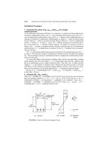
sion and in compression. In Fig. 6, let A s area of tension reinforcement, sq.in. (cm ); A s
2
area of compression reinforcement, sq.in. (cm ); d
distance from compression face of
concrete to centroid of compression reinforcement, in. (mm); f s stress in tension steel,
lb/sq.in. (kPa); f s
stress in compression steel, lb/sq.in. (kPa);
s
strain in compression
steel; p A s /(bd); p
A s
/(bd); q pf y /f c
; M u ultimate moment to be resisted by mem-
ber, in.·lb (N·m); M u1 ultimate-moment capacity of member if reinforced solely in
tension; M u2 increase in ultimate-moment capacity resulting from use of compression
reinforcement; C u1 resultant force in concrete, lb (N); C u2 resultant force in compres-
sion steel, lb (N).
If f
f y , the tension reinforcement may be resolved into two parts having areas of A s
A s
and A s
. The first part, acting in combination with the concrete, develops the moment
M u1 . The second part, acting in combination with the compression reinforcement, devel-
ops the moment M s2 .
To ensure that failure will result from yielding of the tension steel rather than crushing
of the concrete, the ACI Code limits p p
to a maximum value of 0.75p b , where p b has
the same significance as for a singly reinforced beam. Thus the Code, in effect, permits
setting f s
f y if inception of yielding in the compression steel will precede or coincide
with failure of the concrete at balanced-design ultimate moment. This, however, intro-
duces an inconsistency, for the limit imposed on p p
precludes balanced design.
By Eq. 9, q b 0.85(0.80)(87/137) 0.432; q max 0.75(0.432) 0.324; p max
0.324(5/50) 0.0324.
2. Compute M u1 , M u2 , and C u2
Thus, M u 690,000(12) 8,280,000 in.·lb (935,474.4 N·m). Since two rows of tension
bars are probably required, d 24 3.5 20.5 in. (520.7 mm). By Eq. 6, M u1
0.90(14)(20.5) (5000) (0.324)(0.809) 6,940,000 in.·lb (784,081.2 N·m); M u2
2
8,280,000 6,940,000 1,340,000 in.·lb (151,393.2 N·m); C u2 M u2 /(d d
)
1,340,000/(20.5 2.5) 74,400 lb (330,931.2 N).
FIGURE 6. Doubly reinforced rectangular beam.