
Page 220 - Handbook of Civil Engineering Calculations, Second Edition
P. 220
REINFORCED CONCRETE 2.5
To allow for material imperfections, defects in workmanship, etc., the Code intro-
duces the capacity-reduction factor . A section of the Code sets 0.90 with respect to
flexure and 0.85 with respect to diagonal tension, bond, and anchorage.
The basic equations for the ultimate-strength design of a rectangular beam reinforced
solely in tension are
C u 0.85abf c
T u A s f y (1)
[A s /(bd)] f y
q (2)
f c
1.18qd
a 1.18qd c (3)
k 1
a
M u A s f y d (4)
2
M u A s f y d(1 0.59q) (5)
2
M u bd f c
q(1 0.59q) (6)
bdf c [(bdf c ) 2bf c M u / ] 0.5
2
A s (7)
f y
0.85k 1 f c
87,000
p b (8)
f y 87,000 f y
87,000
q b 0.85k 1 (9)
87,000 f y
In accordance with the Code,
87,000
q max 0.75q b 0.6375k 1 (10)
87,000 f y
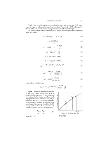
Figure 3 shows the relationship between
M u and A s for a beam of given size. As A s in-
creases, the internal forces C u and T u increase
proportionately, but M u increases by a small-
er proportion because the action line of C u is
depressed. The M u -A s diagram is parabolic,
but its curvature is small. By comparing the
coordinates of two points P a and P b , the fol-
lowing result is obtained, in which the sub-
scripts correspond to that of the given point:
M ua
M ub
> (11)
A sa A sb
FIGURE 3
where A sa < A sb