
Page 219 - Handbook of Civil Engineering Calculations, Second Edition
P. 219
2.4 REINFORCED AND PRESTRESSED CONCRETE ENGINEERING AND DESIGN
Design of Flexural Members by
Ultimate-Strength Method
In the ultimate-strength design of a reinforced-concrete structure, as in the plastic design
of a steel structure, the capacity of the structure is found by determining the load that will
cause failure and dividing this result by the prescribed load factor. The load at impending
failure is termed the ultimate load, and the maximum bending moment associated with
this load is called the ultimate moment.
Since the tensile strength of concrete is relatively small, it is generally disregarded en-
tirely in analyzing a beam. Consequently, the effective beam section is considered to
comprise the reinforcing steel and the concrete on the compression side of the neutral
axis, the concrete between these component areas serving merely as the ligature of the
member.
The following notational system is applied in ultimate-strength design: a depth of
compression block, in. (mm); c distance from extreme compression fiber to neutral
axis, in. (mm); capacity-reduction factor.
Where the subscript u is appended to a symbol, it signifies that the given quantity is
evaluated at ultimate load.
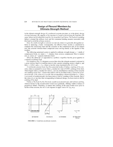
For simplicity (Fig. 2), designers assume that when the ultimate moment is attained at
a given section, there is a uniform stress in the concrete extending across a depth a, and
that f c 0.85f
c , and a k 1 c, where k 1 has the value stipulated in the ACI Code.
A reinforced-concrete beam has three potential modes of failure: crushing of the con-
crete, which is assumed to occur when
c reaches the value of 0.003; yielding of the steel,
which begins when f s reaches the value f y ; and the simultaneous crushing of the concrete
and yielding of the steel. A beam that tends to fail by the third mode is said to be in bal-
anced design. If the value of p exceeds that corresponding to balanced design (i.e., if there
is an excess of reinforcement), the beam tends to fail by crushing of the concrete. But if
the value of p is less than that corresponding to balanced design, the beam tends to fail by
yielding of the steel.
Failure of the beam by the first mode would occur precipitously and without warning,
whereas failure by the second mode would occur gradually, offering visible evidence of
progressive failure. Therefore, to ensure that yielding of the steel would occur prior to
failure of the concrete, the ACI Code imposes an upper limit of 0.75p b on p.
FIGURE 2. Conditions at ultimate moment.