
Page 83 - Handbook of Civil Engineering Calculations, Second Edition
P. 83
1.66 STRUCTURAL STEEL ENGINEERING AND DESIGN
6. Perform the second cycle of moment balancing and distribution
Thus M BA 9.9(15/31) 4.8; M BC 9.9(16/31) 5.1; M CB 1.6(16/25)
1.0; M CD 1.6(9/25) 0.6.
7. Continue the foregoing procedure until the carry-over moments
become negligible
Total the results to obtain the following bending moments: M A 58.2 ft·kips ( 78.91
kN m); M B 45.7 ft·kips ( 61.96 kN·m); M C 66.1 ft·kips ( 89.63 kN·m).
ANALYSIS OF A STATICALLY
INDETERMINATE TRUSS
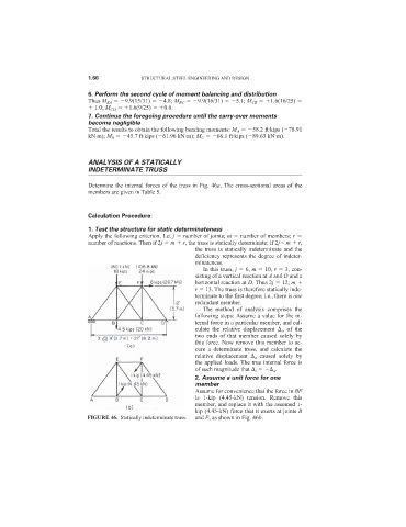
Determine the internal forces of the truss in Fig. 46a. The cross-sectional areas of the
members are given in Table 5.
Calculation Procedure:
1. Test the structure for static determinateness
Apply the following criterion. Let j number of joints; m number of members; r
number of reactions. Then if 2j m r, the truss is statically determinate; if 2j < m r,
the truss is statically indeterminate and the
deficiency represents the degree of indeter-
minateness.
In this truss, j 6, m 10, r 3, con-
sisting of a vertical reaction at A and D and a
horizontal reaction at D. Thus 2j 12; m
r 13. The truss is therefore statically inde-
terminate to the first degree; i.e., there is one
redundant member.
The method of analysis comprises the
following steps: Assume a value for the in-
ternal force in a particular member, and cal-
culate the relative displacement i , of the
two ends of that member caused solely by
this force. Now remove this member to se-
cure a determinate truss, and calculate the
relative displacement a caused solely by
the applied loads. The true internal force is
of such magnitude that i a .
2. Assume a unit force for one
member
Assume for convenience that the force in BF
is 1-kip (4.45-kN) tension. Remove this
member, and replace it with the assumed 1-
kip (4.45-kN) force that it exerts at joints B
FIGURE 46. Statically indeterminate truss. and F, as shown in Fig. 46b.