
Page 78 - Handbook of Civil Engineering Calculations, Second Edition
P. 78
STATICS, STRESS AND STRAIN, AND FLEXURAL ANALYSIS 1.61
Calculation Procedure:
1. Draw the free-body diagram of the beam
Draw the diagram in Fig. 41b. Consider this as a simply supported member carrying a 50-
kip (222.4-kN) load at D and an upward load R B at its center.
2. Evaluate the deflection
Evaluate the deflection at B by applying the equations presented for cases 7 and 8 in the
AISC Manual. With respect to the 50-kip (222.4-kN) load, b 7 ft (2.1 m) and x 14 ft
2
2
2
(4.3 m). If y is in inches and R B is in pounds, y 50,000(7)(14)(28 7 14 )1728/
9
5
3
9
[6(35)(10) 28] R B (28) 1728/[48(35)(10) ] 0.776 (2.26/10 )R B .
3. Express the deflection in terms of the spring constant
The deflection at B is, by proportion, y/1 R B /100,000; y R B /100,000.
4. Equate the two deflection expressions, and solve for the
upward load
5
5
5
Thus R B /10 0.776 (2.26/10 )R B ; R B 0.776(10) /3.26 23,800 lb (105,862.4 N).
5. Calculate the reactions R A and R C by taking moments
We have M C 28R A 50,000(21) 23,800(14) 0; R A 25,600 lb (113,868.8 N);
M A 50,000(7) 23,800(14) 28R C 0; R C 600 lb (2668.8 N).
6. Construct the shear and moment diagrams
Construct these diagrams as shown in Fig. 41. Then M D 7(25,600) 179,200 lb·ft
(242,960 N·m); M B 179,200 7(24,400) 8400 lb·ft (11,390.4 N·m).
MAXIMUM BENDING STRESS IN BEAMS
JOINTLY SUPPORTING A LOAD
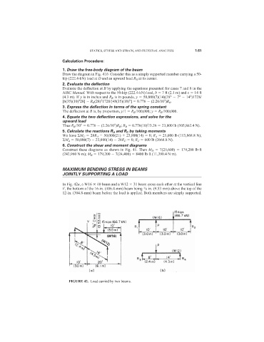
In Fig. 42a, a W16 40 beam and a W12 31 beam cross each other at the vertical line
V, the bottom of the 16-in. (406.4-mm) beam being /8 in. (9.53 mm) above the top of the
3
12-in. (304.8-mm) beam before the load is applied. Both members are simply supported.
FIGURE 42. Load carried by two beams.