Page 76 - Handbook of Civil Engineering Calculations, Second Edition
P. 76

STATICS, STRESS AND STRAIN, AND FLEXURAL ANALYSIS  1.59
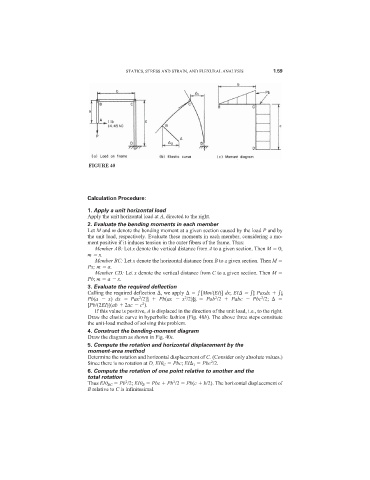


                              FIGURE 40


                              Calculation Procedure:

                              1. Apply a unit horizontal load
                              Apply the unit horizontal load at A, directed to the right.
                              2. Evaluate the bending moments in each member
                              Let M and m denote the bending moment at a given section caused by the load P and by
                              the unit load, respectively. Evaluate these moments in each member, considering a mo-
                              ment positive if it induces tension in the outer fibers of the frame. Thus:
                                Member AB: Let x denote the vertical distance from A to a given section. Then M   0;
                              m   x.
                                Member BC: Let x denote the horizontal distance from B to a given section. Then M
                              Px; m   a.
                                Member CD: Let x denote the vertical distance from C to a given section. Then M
                              Pb; m   a   x.
                              3. Evaluate the required deflection
                                                                                     b        c
                              Calling the required deflection  , we apply     [Mm/(EI)] dx; EI     0 Paxdx     0
                                                                        2
                                                                 c
                                                              2
                                                                                       2
                                                  b
                              Pb(a    x)  dx    Pax /2] 0   Pb(ax    x /2)] 0   Pab /2    Pabc    Pbc /2;
                                               2
                                                2
                              [Pb/(2EI)](ab   2ac   c ).
                                If this value is positive, A is displaced in the direction of the unit load, i.e., to the right.
                              Draw the elastic curve in hyperbolic fashion (Fig. 40b). The above three steps constitute
                              the unit-load method of solving this problem.
                              4. Construct the bending-moment diagram
                              Draw the diagram as shown in Fig. 40c.
                              5. Compute the rotation and horizontal displacement by the
                              moment-area method
                              Determine the rotation and horizontal displacement of C. (Consider only absolute values.)
                                                                       2
                              Since there is no rotation at D, EI	 C   Pbc; EI  1   Pbc /2.
                              6. Compute the rotation of one point relative to another and the
                              total rotation
                                          2
                                                          2
                              Thus EI	 BC   Pb /2; EI	 B   Pbc   Pb /2   Pb(c   b/2). The horizontal displacement of
                              B relative to C is infinitesimal.
   71   72   73   74   75   76   77   78   79   80   81