
Page 72 - Handbook of Civil Engineering Calculations, Second Edition
P. 72
STATICS, STRESS AND STRAIN, AND FLEXURAL ANALYSIS 1.55
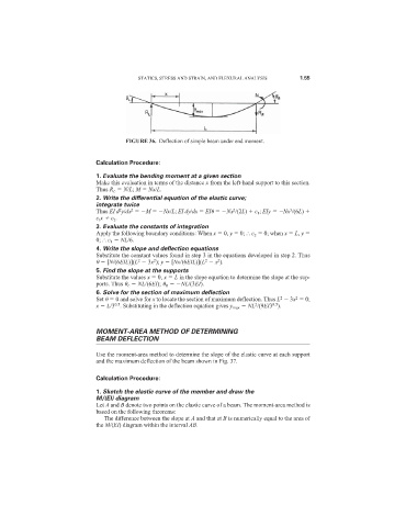
FIGURE 36. Deflection of simple beam under end moment.
Calculation Procedure:
1. Evaluate the bending moment at a given section
Make this evaluation in terms of the distance x from the left-hand support to this section.
Thus R L N/L; M Nx/L.
2. Write the differential equation of the elastic curve;
integrate twice
3
2
2
Thus EI d y/dx M Nx/L; EI dy/dx EI Nx /(2L) c 1 ; EIy Nx /(6L)
2
c l x c 2 .
3. Evaluate the constants of integration
Apply the following boundary conditions: When x 0, y 0; c 2 0; when x L, y
0; c 1 NL/6.
4. Write the slope and deflection equations
Substitute the constant values found in step 3 in the equations developed in step 2. Thus
2
2
2
2
[N/(6EIL)](L 3x ); y [Nx/(6EIL)](L x ).
5. Find the slope at the supports
Substitute the values x 0, x L in the slope equation to determine the slope at the sup-
ports. Thus L NL/(6EI); R NL/(3EI).
6. Solve for the section of maximum deflection
2
2
Set 0 and solve for x to locate the section of maximum deflection. Thus L 3x 0;
0.5
2
0.5
x L/3 . Substituting in the deflection equation gives y max NL /(9EI3 ).
MOMENT-AREA METHOD OF DETERMINING
BEAM DEFLECTION
Use the moment-area method to determine the slope of the elastic curve at each support
and the maximum deflection of the beam shown in Fig. 37.
Calculation Procedure:
1. Sketch the elastic curve of the member and draw the
M/(EI) diagram
Let A and B denote two points on the elastic curve of a beam. The moment-area method is
based on the following theorems:
The difference between the slope at A and that at B is numerically equal to the area of
the M/(EI) diagram within the interval AB.