Page 70 - Handbook of Civil Engineering Calculations, Second Edition
P. 70

STATICS, STRESS AND STRAIN, AND FLEXURAL ANALYSIS  1.53


                              (40.03 kN);  W   18,000   9000   27,000 lb (120.10 kN). Then x 1   ( /3)(12)   8.0 ft
                                                                                   2
                                      2
                              (2.44 m); x   12   1.5   13.5 ft (4.11 m).
                              2. Find the magnitude and location of the resultant of the
                              hydrostatic pressure
                                                               2
                                                    2
                              Calling the resultant H   /2wh   /2(62.4)(20)   12,480 lb (55.51 kN), where w   weight
                                                      1
                                                1
                                       3
                                            3
                              of water, lb/ft (N/m ), and h   water height, ft (m), then y   ( /3)(20)   6.67 ft (2.03 m).
                                                                          1
                              3. Compute the moment of the loads with respect to the
                              base centerline
                              Thus, M   18,000(8   7.5)   9000(13.5   7.5)   12,480(6.67)   20,200 lb·ft (27,391
                              N·m) counterclockwise.
                              4. Compute the section modulus of the base
                                                                    3
                                                                           3
                                                  2
                                                             2
                              Use the relation S   ( /6)bd   ( /6)(1)(15)   37.5 ft (1.06 m ).
                                              1
                                                     1
                              5. Determine the soil pressure at the dam toe and heel
                              Compute the soil pressure caused by the combined axial load and bending. Thus f 1   W/A
                                M/S   27,000/15   20,200/37.5   2339 lb/sq.ft. (111.99 kPa); f 2   1800   539   1261
                              lb/sq.ft. (60.37 kPa).
                              6. Verify the computed results
                              Locate the resultant R of the trapezoidal pressure prism, and take its moment with respect to the
                              centerline of the base. Thus R   27,000 lb (120.10 kN); m   (15/3)[(2   1261   2339)/(1261
                                2339)]   6.75 ft (2.05 m); M R   27,000(7.50   6.75)   20,200 lb·ft (27,391 N·m). Since
                              the applied and resisting moments are numerically equal, the computed results are correct.
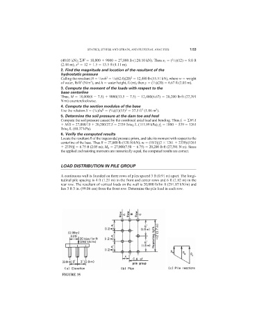
                              LOAD DISTRIBUTION IN PILE GROUP
                              A continuous wall is founded on three rows of piles spaced 3 ft (0.91 m) apart. The longi-
                              tudinal pile spacing is 4 ft (1.21 m) in the front and center rows and 6 ft (1.82 m) in the
                              rear row. The resultant of vertical loads on the wall is 20,000 lb/lin ft (291.87 kN/m) and
                              lies 3 ft 3 in. (99.06 cm) from the front row. Determine the pile load in each row.


                               FIGURE 35
   65   66   67   68   69   70   71   72   73   74   75