
Page 68 - Handbook of Civil Engineering Calculations, Second Edition
P. 68
STATICS, STRESS AND STRAIN, AND FLEXURAL ANALYSIS 1.51
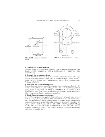
FIGURE 32. Transverse section of FIGURE 33. Curved member in bending.
a post.
2. Compute the section modulus
Determine the section modulus of the rectangular cross section with respect to each axis.
2
2
3
2
3
1
1
1
Thus S x ( /6)bd ( /6)(18)(24) 1728 in (28,321.9 cm ); S y ( /6)(24)(18) 1296
3
3
in (21,241 cm ).
3. Compute the stresses produced
Compute the uniform stress caused by the concentric load and the stresses at the edges
caused by the bending moments. Thus f 1 P/A 100,000/[18(24)] 231 lb/sq.in. (1592.7
kPa); f x M x /S x 200,000/1728 116 lb/sq.in. (799.8 kPa); f y M y /S y 100,000/1296
77 lb/sq.in. (530.9 kPa).
4. Determine the stress at each corner
Combine the results obtained in step 3 to obtain the stress at each corner. Thus f A 231
116 77 424 lb/sq.in. (2923.4 kPa); f B 231 116 77 270 lb/sq.in. (1861.5
kPa); f C 231 116 77 192 lb/sq.in. (1323.8 kPa); f D 231 116 77 38
lb/sq.in. (262.0 kPa). These stresses are all compressive because a positive stress is con-
sidered compressive, whereas a tensile stress is negative.
5. Check the computed corner stresses
Use the following equation that applies to the special case of a rectangular cross section: f
(P/A)(1 ± 6e x /d x 6e y /d y ), where e x and e y eccentricity of load with respect to the x
and y axes, respectively; d x and d y side of rectangle, in. (mm), normal to x and y axes,
respectively. Solving for the quantities within the brackets gives 6e x /d x 6(2)/24 0.5;
6e y /d y 6(1)/18 0.33. Then f A 231(1 0.5 0.33) 424 lb/sq.in. (2923.4 kPa); f B
231(1 0.5 0.33) 270 lb/sq.in. (1861.5 kPa); f C 231(1 0.5 0.33) 192
lb/sq.in. (1323.8 kPa); f D 231(1 0.5 0.33) 38 lb/sq.in. (262.0 kPa). These results
verify those computed in step 4.