
Page 64 - Handbook of Civil Engineering Calculations, Second Edition
P. 64
STATICS, STRESS AND STRAIN, AND FLEXURAL ANALYSIS 1.47
In the actual beam, the maximum timber stress, which occurs at the back of the chan-
nel, is even less than 880 lb/sq.in. (6067.6 kPa). Therefore, the strength of the member is
controlled by the allowable stress in the steel.
7. Compare the capacity of the original and reinforced beams
Let subscripts 1 and 2 denote the original and reinforced beams, respectively. Compute
the capacity of these members, and compare the results. Thus M 1 fI/c 1200(1152)/6
230,000 lb·in. (25,985.4 N·m); M 2 880(7626)/8.40 799,000 lb·in. (90,271.02
1
N·m); M 2 /M 1 799,000/230,000 3.47. Thus, the reinforced beam is nearly 3 /2 times
as strong as the original beam, before reinforcing.
BEAM SHEAR FLOW AND
SHEARING STRESS
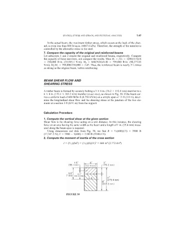
A timber beam is formed by securely bolting a 3 6 in. (76.2 152.4 mm) member to a
6 8 in. (152.4 203.2 mm) member (exact size), as shown in Fig. 30. If the beam car-
ries a uniform load of 600 lb/lin ft (8.756 kN/m) on a simple span of 13 ft (3.9 m), deter-
mine the longitudinal shear flow and the shearing stress at the juncture of the two ele-
ments at a section 3 ft (0.91 m) from the support.
Calculation Procedure:
1. Compute the vertical shear at the given section
Shear flow is the shearing force acting on a unit distance. In this instance, the shearing
force on an area having the same width as the beam and a length of 1 in. (25.4 mm) meas-
ured along the beam span is required.
1
Using dimensions and data from Fig. 30, we find R /2(600)(13) 3900 lb
(17,347.2 N); V 3900 3(600) 2100 lb (9340.8 N).
2. Compute the moment of inertia of the cross section
4
3
4
3
I ( /12)(bd ) ( /12)(6)(11) 666 in (2.772 dm )
1
1
FIGURE 30