Page 63 - Handbook of Civil Engineering Calculations, Second Edition
P. 63

1.46            STRUCTURAL STEEL ENGINEERING AND DESIGN
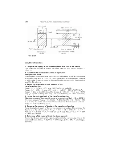


                               FIGURE 29


                            Calculation Procedure:
                            1. Compute the rigidity of the steel compared with that of the timber
                                                                                     6
                            Let n   the relative rigidity of the steel and timber. Then n   E s /E t   (30   10 )/(1.2
                             6
                            10 )   25.
                            2. Transform the composite beam to an equivalent
                            homogeneous beam
                            To accomplish this transformation, replace the steel with timber. Sketch the cross section
                            of the transformed beam as in Fig. 29b. Determine the sizes of the hypothetical elements
                            by retaining the dimensions normal to the axis of bending but multiplying the dimensions
                            parallel to this axis by n.
                            3. Record the properties of each element of the
                            transformed section
                                                                 2
                                            1
                            Element 1: A   25(7)( /2)   87.5 sq.in. (564.55 cm ); I 0 is negligible.
                                                            2
                                                                       3
                                                                               4
                                                                                        4
                                                                 1
                            Element 2: A   8(12)   96 sq.in. (619.4 cm ); I 0   /2(8)12   1152 in (4.795 dm ).
                            Element 3: Refer to the AISC Manual for the data; A   25(2.85)   71.25 sq.in. (459.71
                                                       4
                              2
                                               4
                            cm ); I 0   25(0.98)   25 in (1040.6 cm ); a   0.55 in. (13.97 mm); b   2.09 in. (53.09 mm).
                            4. Locate the centroidal axis of the transformed section
                            Take static moments of the areas with respect to the centerline of the 8   12 in. (203.2
                            304.8 mm) rectangle. Then y m   [87.5(6.25)   71.25(6.55)]/(87.5   96   71.25)   0.31
                            in. (7.87 mm). The neutral axis of the composite section is at the same location as the cen-
                            troidal axis of the transformed section.
                            5. Compute the moment of inertia of the transformed section
                            Apply the relation in step 3 of the previous calculation procedure. Then compute the
                                                                                         2
                            distance  c to the outermost fiber. Thus,  I   1152    25    87.5(6.25    0.31)
                                                                     4
                                                            4
                                  2
                                                    2
                            96(0.31)   71.25(6.55   0.31)   7626 in (31.74 dm ). Also, c   0.31   6   2.09
                              8.40 in. (213.36 mm).
                            6. Determine which material limits the beam capacity
                            Assume that the steel is stressed to capacity, and compute the corresponding stress in the
                            transformed beam. Thus,  f   22,000/25    880 lb/sq.in. (6067.6 kPa) < 1200 lb/sq.in.
                            (8274 kPa).
   58   59   60   61   62   63   64   65   66   67   68